
 Wenzhou Lita Electric Co., Ltd.
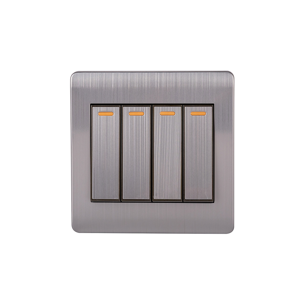
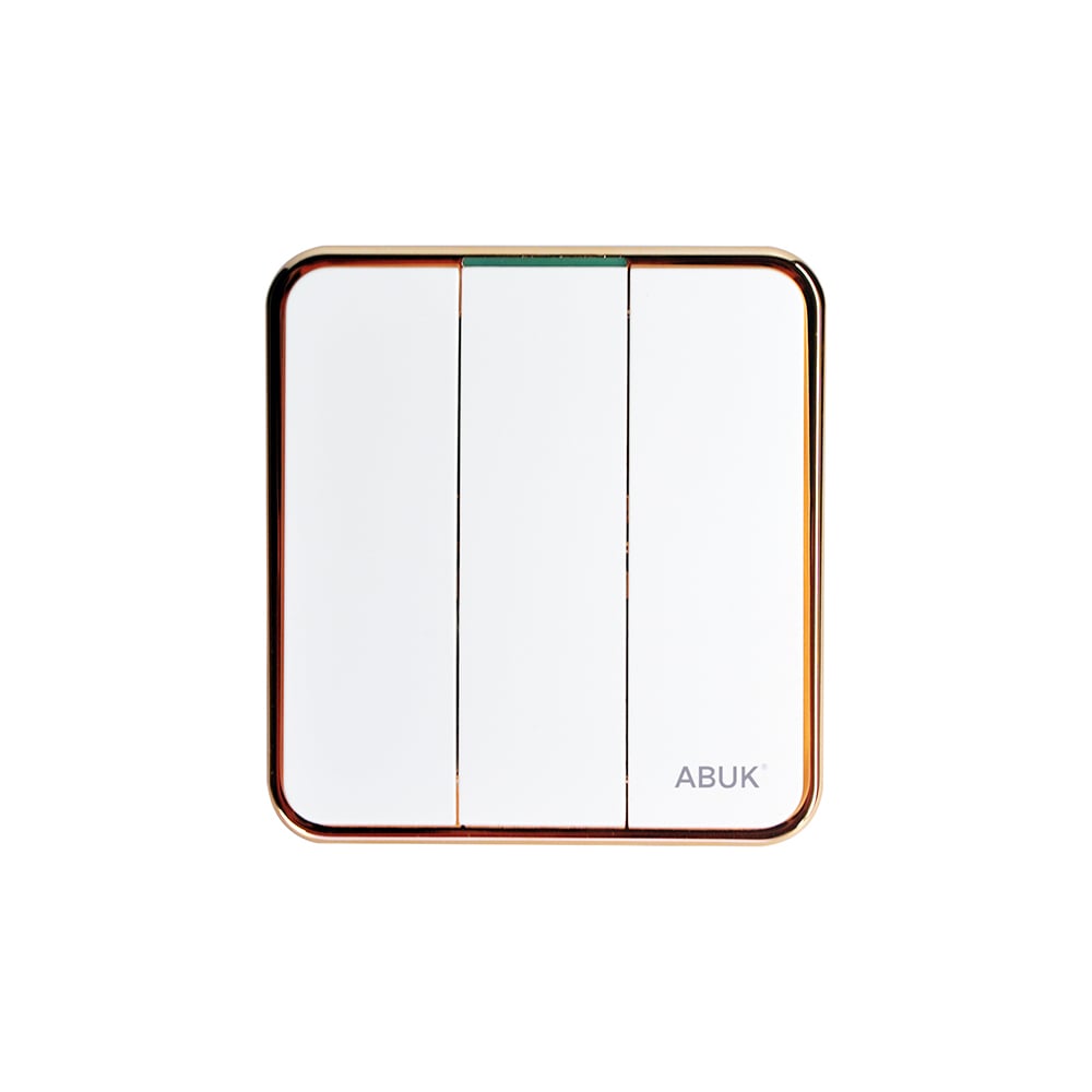
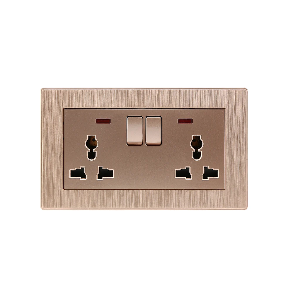
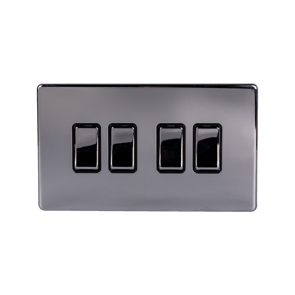

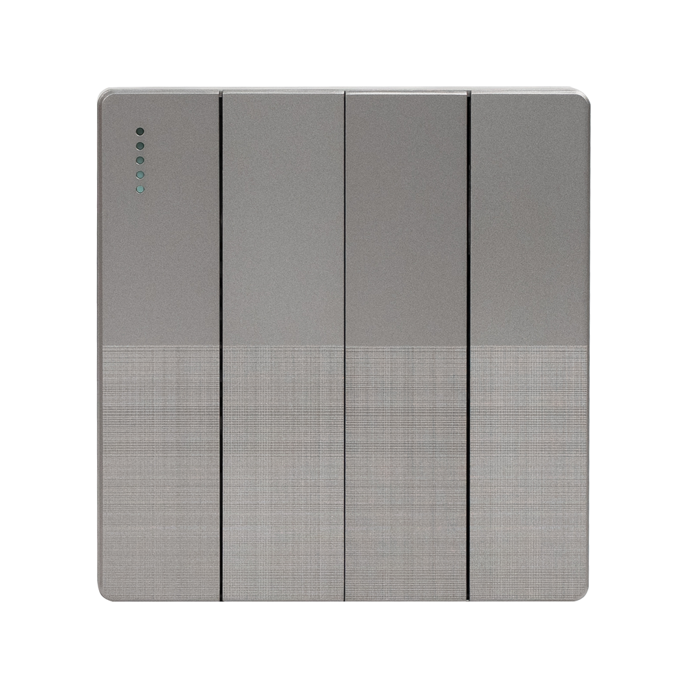
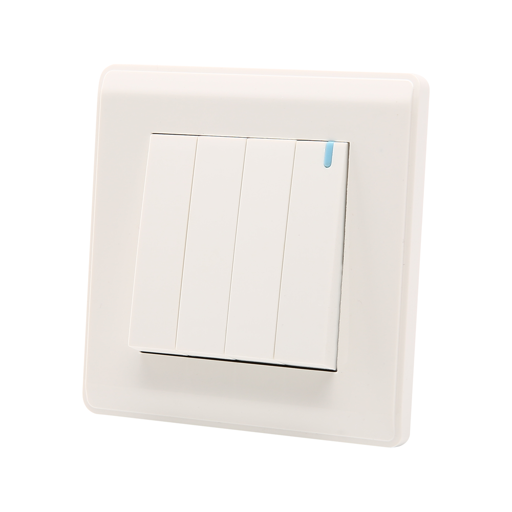
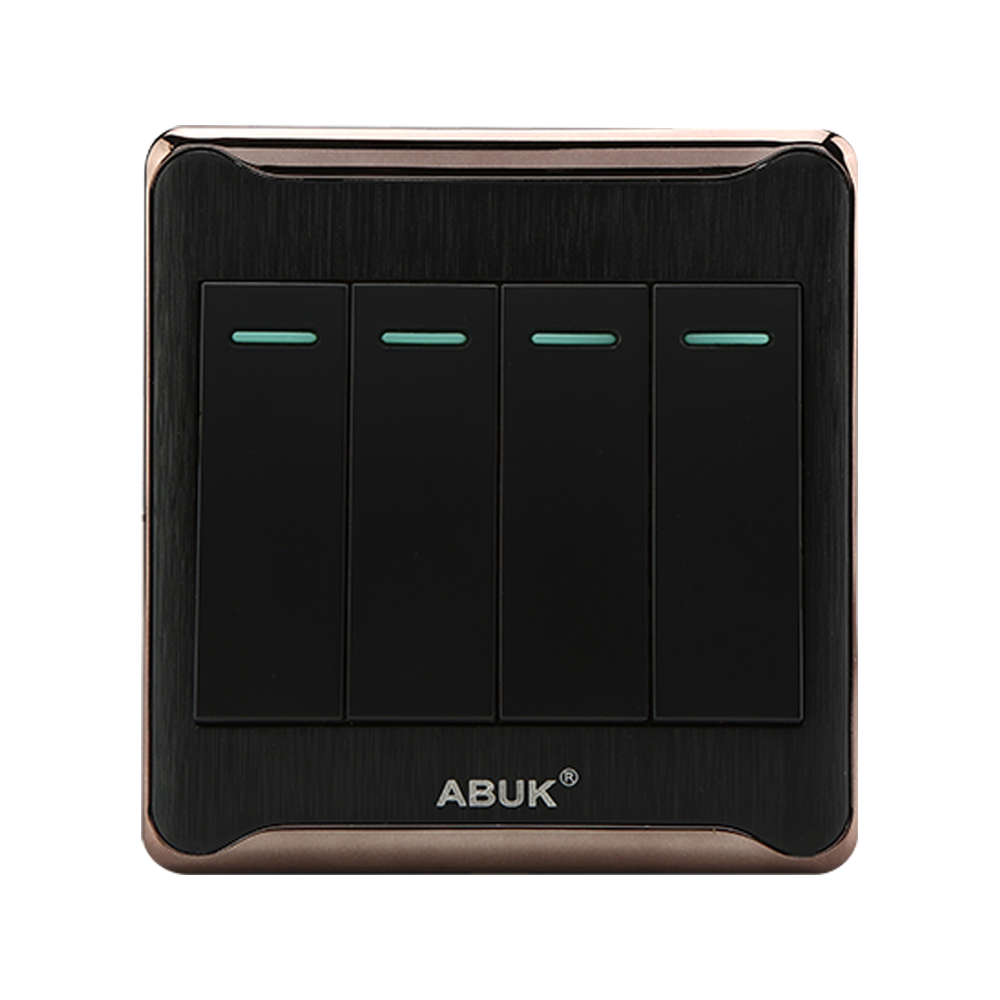
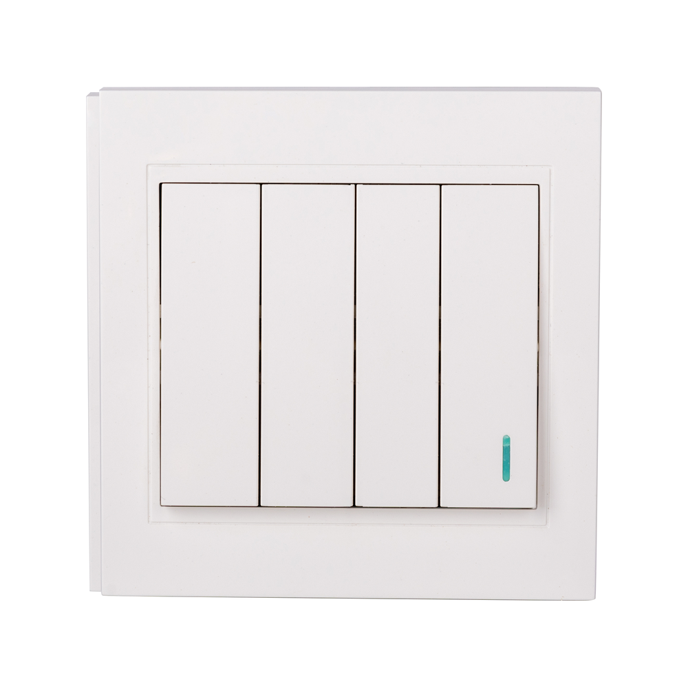

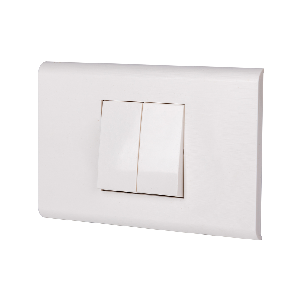
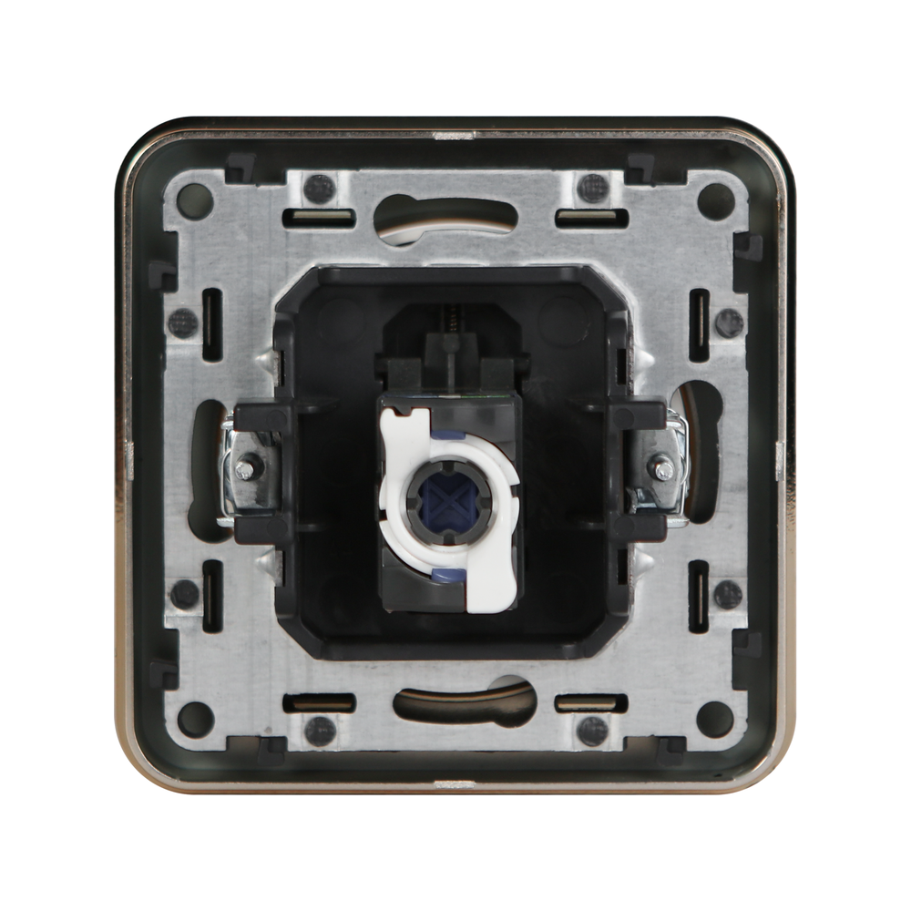

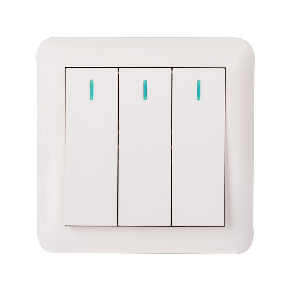
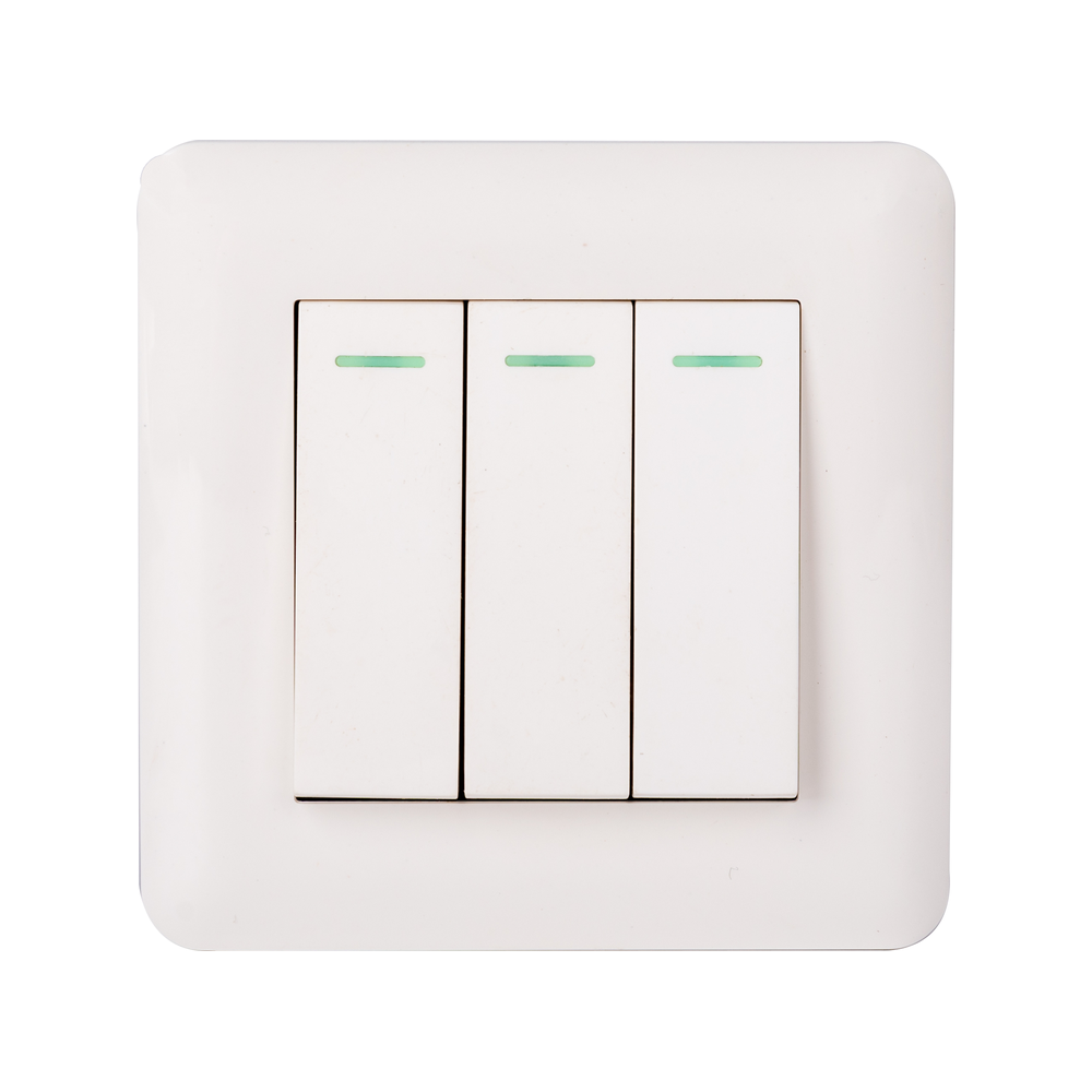
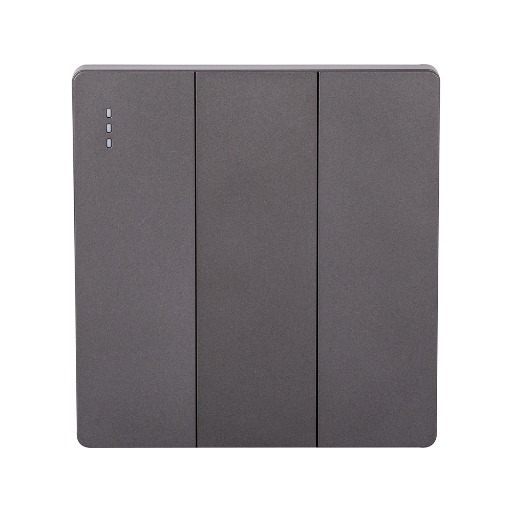
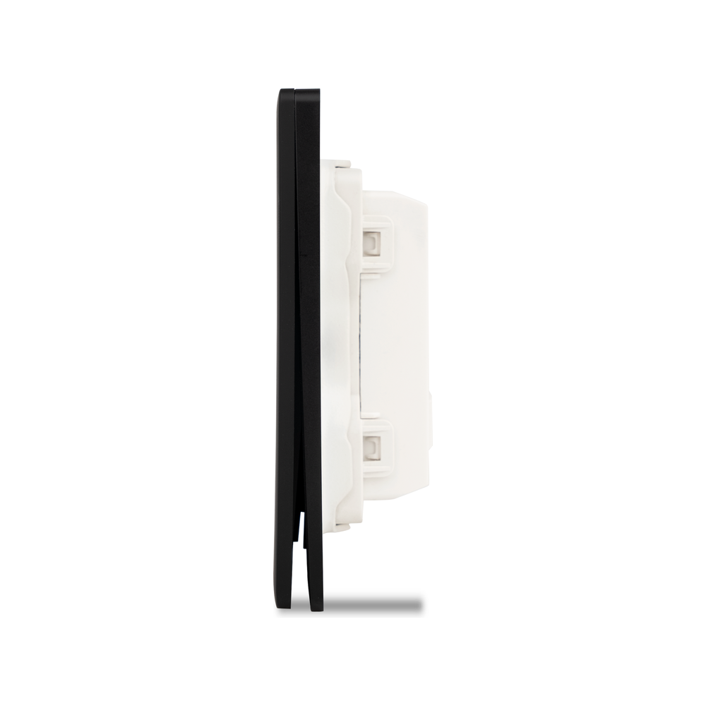
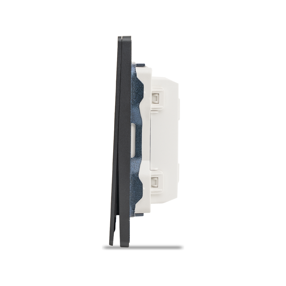

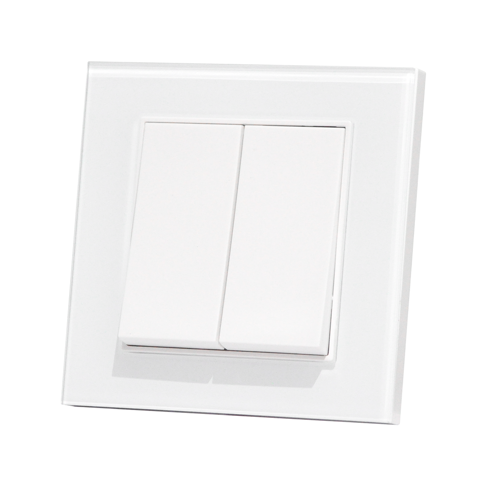





Diagrama de ligação do interruptor de 3 vias: alimentação e iluminação
Quando um engenheiro de instalações em Chicago analisou a reforma de um corredor, a iluminação funcionava a partir de um interruptor, mas não funcionava a partir do outro. O mapeamento revelou que a fonte de alimentação estava na caixa da luminária, enquanto os terminais do interruptor haviam sido dimensionados como se a energia entrasse pelo primeiro interruptor. A Diagrama de ligação do interruptor de 3 vias para alimentação da luz O arranjo é, portanto, antes de mais nada, um problema de topologia e identificação do que um problema de produto. Este guia explica a lógica para o planejamento profissional e a comunicação de falhas. Ele não autoriza trabalhos em circuitos energizados: isole o circuito, siga as normas locais e o diagrama do fabricante, e recorra a um eletricista qualificado.
Resposta Rápida: Em um circuito norte-americano descrito por um Diagrama de ligação do interruptor de 3 vias para alimentação da luz, a linha de alimentação e o neutro chegam à caixa da luminária. Um condutor da linha alcança o terminal comum de um interruptor 3-way, dois condutores de ligação interligam os interruptores e o outro terminal comum retorna um circuito comutado para a lâmpada. A disposição exata dos cabos varia conforme o método de fiação e as normas. “Comum” é o único terminal de inversão; “ligações” são os condutores em pares entre as posições dos interruptores. Confirme esses papéis com base no desenho aprovado, nas marcações do dispositivo e em um teste realizado com os equipamentos desenergizados por uma pessoa qualificada. A terminologia IEC/Reino Unido é diferente: essa função é geralmente chamada de comutação bidirecional.
A decisão prática é não copiar as cores de um esboço genérico. Confirme o mercado de destino, a tensão nominal, a classificação do interruptor, o tipo de carga, a capacidade da caixa e as instruções do fabricante. A norma IEC 60669-1 abrange interruptores elétricos fixos de uso geral, enquanto as regras de instalação são estabelecidas pelo código localmente adotado, como a NFPA 70 nos Estados Unidos.
Assim que a topologia for confirmada, o Guia de planejamento para a substituição de interruptores de luz Ajuda a coordenar o isolamento, as dimensões das caixas e a documentação de entrega.
Interruptor de 3 vias na luminária
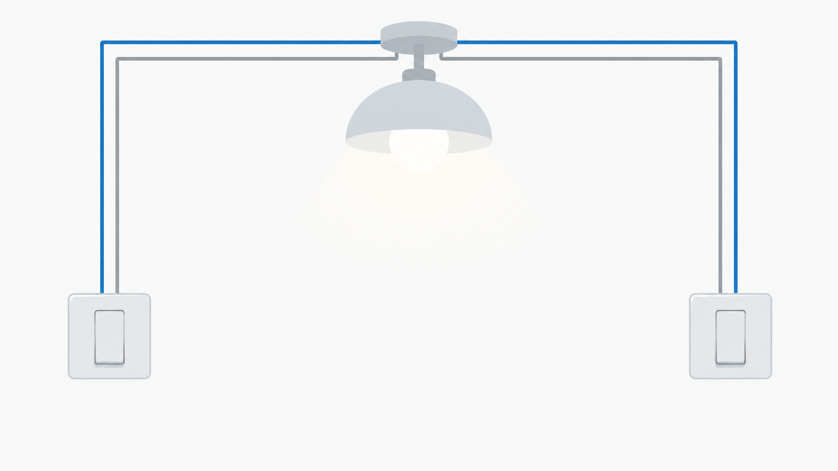
“Alimentação na luminária” refere-se ao ponto onde a alimentação do circuito derivado entra pela primeira vez, e não à localização da lâmpada. A fase e o neutro chegam à caixa de passagem ou de derivação no teto, enquanto dois interruptores de parede controlam a fase por meio de um circuito interligado entre eles. O neutro continua até a luminária; a fase comutada retorna do segundo interruptor. O condutor de proteção é separado e nunca pode substituir o neutro.
Analise a topologia como quatro nós funcionais: linha de alimentação, luminária, interruptor A e interruptor B. O terminal comum do interruptor A recebe o circuito controlado; o terminal comum do interruptor B retorna o circuito selecionado à luminária. Os dois terminais de ligação formam um par entre os interruptores A e B. Um diagrama genérico deve indicar as funções e os nomes dos terminais, sem induzir o leitor a inferir uma cor segura para os condutores.
Na América do Norte, “3-way” significa dois interruptores unipolares de dupla ação utilizados em conjunto, sem marcação de ligado/desligado. Na prática da IEC e do Reino Unido, “interruptor bidirecional” descreve a mesma função de duas localidades. Indique tanto a função quanto o padrão de destino nos documentos de compra.
Qual é o terminal comum em um interruptor de 3?
Cada dispositivo 3-way possui um terminal comum e dois terminais de trânsito. O comum geralmente é um parafuso de cor diferente ou um terminal marcado como COM, L ou C, mas as marcações variam conforme o fabricante. Não é seguro identificá-lo apenas pela cor do parafuso em um dispositivo não verificado. Os terminais de trânsito são os dois terminais que alternam a conexão com o comum à medida que a chave é acionada; eles formam um par funcional, sem necessariamente terem uma cor específica de isolamento.
For project documentation, label conductors by their circuit role at both ends after the circuit is isolated and verified dead. Record the cable route, terminal marking and destination box in the as-built drawing. A re-marked white conductor, a multi-core cable or an older installation can defeat assumptions based on convention. The electrician should compare the actual device data sheet with the drawing before landing any conductor.
Continuity testing can help distinguish a traveler pair or confirm a route, but it is a qualified-person task. The circuit must be isolated, secured against re-energization and tested with suitable equipment; continuity does not replace voltage, insulation, protective-conductor or final functional checks.
3 Way Switch Wiring Diagram Power at Switch
| Planning point | Power at light | Power at first switch | Por que isso importa |
|---|---|---|---|
| Supply entry | Line and neutral enter the luminaire or junction box | Line and neutral are available at the switch box | The cable route and box roles change. |
| Common role | One common is fed through the switch path; the other returns switched line to the light | One common receives line; the other sends switched line onward | Terminal identity must come from the approved diagram. |
| Neutral at switch | May not be present at either switch, depending on the cable method | Often available at the supply switch box | Smart controls and sensors need a verified neutral requirement. |
| Typical documentation risk | Assuming the nearest switch is the source point | Assuming every circuit has the same traveler route | Wrong assumptions create nonfunctional or unsafe rework. |
| Verification focus | Map the luminaire box, switch commons and traveler pair | Map the supply, switched leg and traveler pair | Use device markings, de-energized tests and local code review. |
Both topologies can provide two-location control, but they are not interchangeable cable-for-cable. A replacement device may also have electronic requirements that differ from a mechanical switch. Treat the existing wiring as an installation to be identified, not as a template to copy.
3 Way Switch Wiring Diagram
Start with symbols and functions rather than physical orientation. Trace the supply line to the first common, follow the two traveler paths to the second switch, and trace the second common back to the lamp input. Then trace neutral to the luminaire and confirm the protective conductor and box bonding path. A text-free diagram should preserve these relationships while leaving conductor labels to the verified project schedule.
Check rated voltage and current, load category, terminal arrangement, wire range, tightening method and any derating or multi-gang limits. IEC 60669-1 is a product standard, not an installation code. In North American projects, NFPA 70 and local amendments govern conductors, boxes, grounding, protection and workmanship; other markets require their own adopted rules.
Do not infer a measurement from a drawing. The diagram describes intended connectivity; a qualified electrician must verify absence of voltage, conductor identity, insulation condition and protective continuity on the actual circuit. Any discrepancy should stop the work and trigger a revised drawing or manufacturer clarification.
How to Identify Wires in a 3 Way Switch
| Sintoma | Possible planning or installation cause | Qualified action |
|---|---|---|
| Light works from only one switch position | Common and traveler roles may be mixed, or one traveler path is open | Isolate, verify the device terminals and test the path against the approved drawing. |
| Neither switch controls the light | Open supply, switched leg, neutral or protective issue; failed device is only one possibility | Check the complete circuit and protection; do not assume a replacement switch will fix it. |
| Breaker or protective device trips | Shorted conductor, damaged insulation, misidentified neutral, overload or incompatible control | Stop, isolate and investigate under the applicable code and manufacturer instructions. |
| Switch feels hot or crackles | Loose termination, overload, unsuitable load or damaged device | Remove from service and have a qualified electrician inspect torque, rating and load. |
| Electronic switch will not operate | Neutral, minimum-load, compatibility or traveler-terminal requirement is unmet | Compare the exact model guide with the measured installation conditions. |

These are diagnostic categories, not permission to open an energized box. Capture the symptom, device model, circuit protection, load type and drawing revision so the electrician or manufacturer receives usable evidence.
3 Way Switch Wiring Diagram Power at Light PDF
- State the market and terminology: North American 3-way or IEC/UK two-way, plus voltage and frequency.
- Match switch rating and load category to the luminaire, including LED-driver requirements.
- Request the exact terminal diagram, installation sheet, declarations and conformity documents for the model.
- Confirm box depth, conductor range, terminal torque, derating and traveler routing.
- Require isolation, identification, testing and qualified final sign-off under the destination code.
A ABUK 1-gang 2-way rocker switch series can be reviewed when an IEC-style two-location switching product is being specified; the exact model, market and documentation still need confirmation. For broader device selection, compare the linha de interruptores e tomadas de parede against the project schedule rather than choosing by faceplate appearance.
Perguntas frequentes
Diagrama de ligação do interruptor de 3 vias: alimentação e iluminação
Conceptually, the line and neutral enter the light box; a controlled line path uses one switch common, two travelers between the switches, and the second switch common returns the switched leg to the luminaire. The cable arrangement and conductor identification depend on the wiring method and local code. A qualified electrician must isolate and verify the actual circuit using the approved manufacturer diagram.
Qual é o terminal comum em um interruptor de 3?
It is the single changeover terminal on each switch, usually marked COM, L or C, and often distinguished by the manufacturer. One common belongs to the incoming controlled path and the other to the switched return in a power-at-light topology. Never rely on color alone; use the device marking and approved drawing.
How to Identify Traveler Wires in 3 Way Switch
Travelers are the two conductors that connect the traveler terminals of both switches and alternate with switch position. Their insulation color is not a universal identifier, especially in older or multi-core wiring. After isolation and lockout, a qualified person can label the conductors and perform continuity testing with suitable equipment.
How to Trace 3 Way Switch Wiring
The usual categories are a misidentified common, an open traveler, a loose termination or a device that does not match the circuit. It can also indicate a damaged cable or control incompatibility. Stop live troubleshooting and have the entire path checked against the drawing, device instructions and local code.
Referências e próximo passo
- Visão geral da segurança elétrica da OSHA
- NFPA 70: Código Nacional de Eletrificação
- IEC 60669-1: Interruptores para instalações elétricas domésticas e similares fixas
- Leviton 3-way switch instruction sheet (manufacturer example)
A dependable 3-way specification starts with topology: locate the source, identify both commons, map travelers, then verify product and code. Do not trade isolation or qualified testing for a quicker drawing or familiar wire color. ABUK’s 2-way versus 3-way switch explanation adds terminology context; when the circuit, market and model are defined, Contate o ABUK for documentation and sourcing discussion.
Conclusão
A Diagrama de ligação do interruptor de 3 vias para alimentação da luz is defined by the supply entry and the assignment of the two commons and traveler pair, not by generic color code. Identify the regional terminology, confirm luminaire-box topology, match switch rating and load, and verify the manufacturer diagram. Isolation, labeling, de-energized testing and final inspection belong to a qualified electrician. For procurement teams, that sequence also keeps the product data sheet, cable schedule and inspection record aligned before a device reaches the site. ABUK can support sourcing with wall-switch documentation; installation remains tied to the approved design and local requirements today.