
 Wenzhou Lita Electric Co., Ltd.
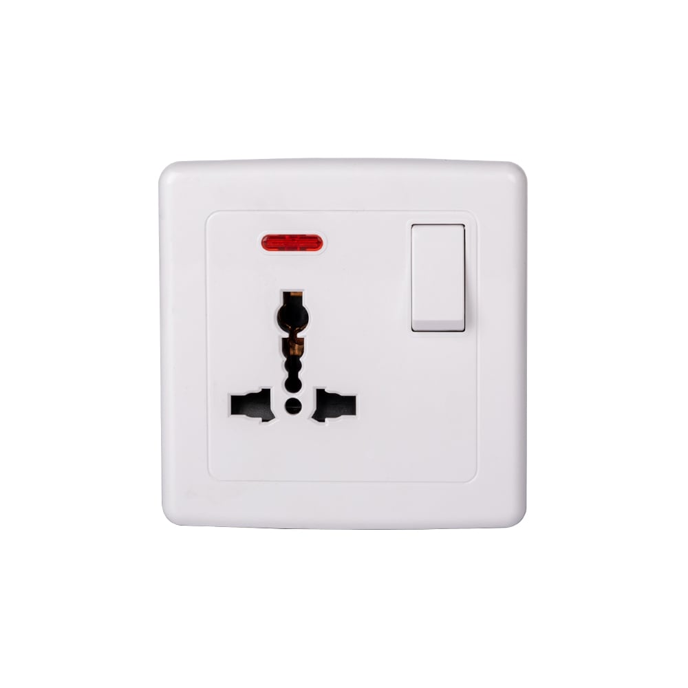
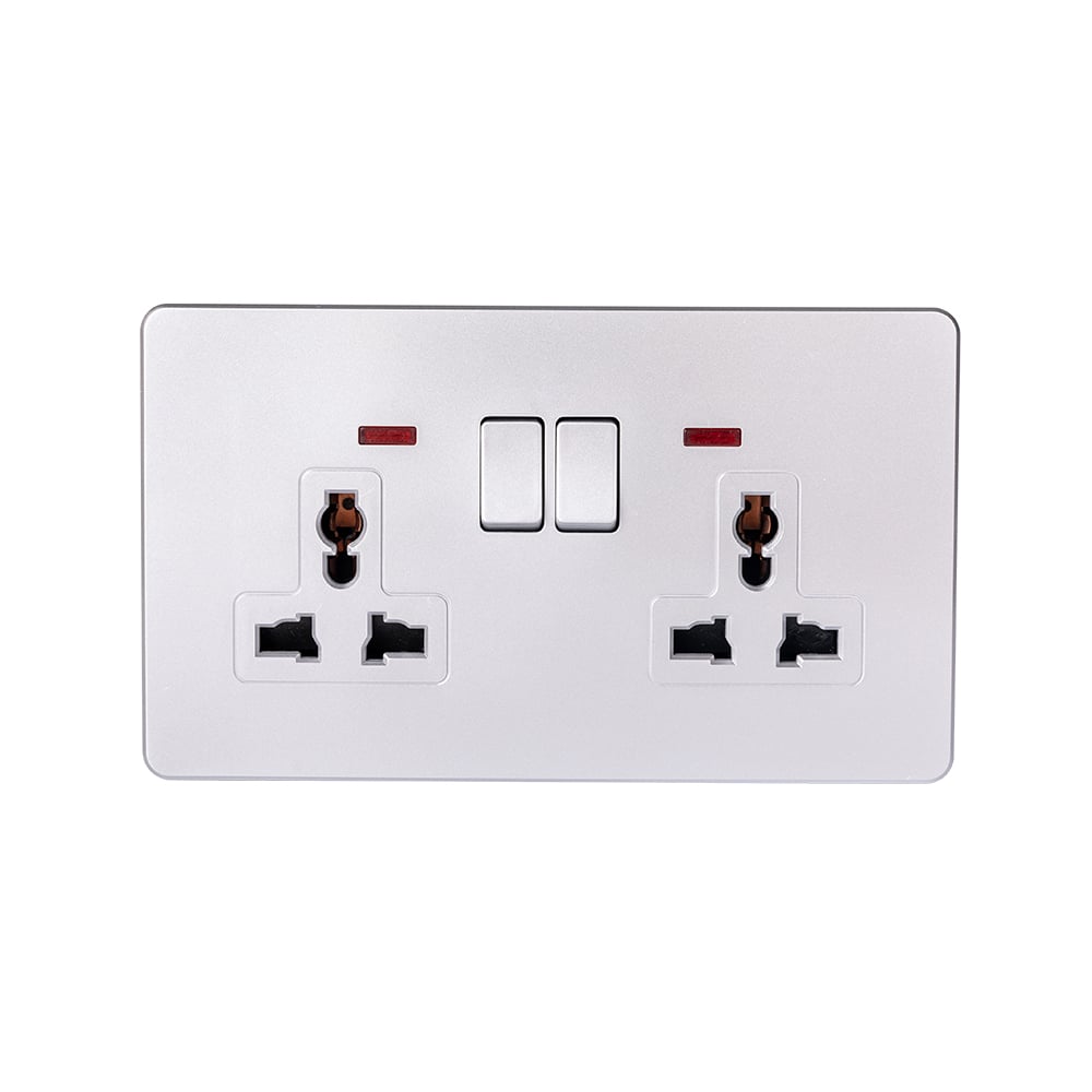
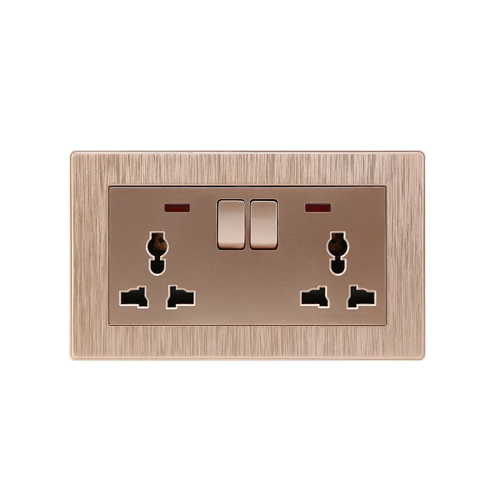



How to Wire a Switch Outlet Combo?
A receptacle that loses power whenever the light is switched off usually points to a wiring arrangement that does not match the intended use. For a contractor specifying an always-live outlet beside a lighting switch, the important question is not which screw looks like the old device’s terminal. It is whether the replacement’s approved diagram keeps the receptacle on a constant supply while the switch controls a separate load. An unsuitable terminal arrangement, a missing neutral, or an overcrowded box can turn a simple replacement into extra installation work. This guide explains the checks that determine whether that configuration is possible.
The short answer is that a switch outlet combo with an always-live receptacle needs the receptacle connected to an unswitched line and its circuit neutral, while the switch receives line and supplies the light through a separate switched conductor. Equipment grounding remains separate from neutral. In a typical single-circuit installation, the two functions share the same branch-circuit supply, but the manufacturer’s diagram determines whether an approved internal link or external connection feeds them. Before selecting the device, a qualified electrician must confirm the conductors, ratings, terminal instructions, and applicable installation code. This is not a universal screw-by-screw wiring diagram.
A combination device puts a switch and a receptacle in one assembly; it does not necessarily mean the switch controls that receptacle. OSHA 29 CFR 1910.303(b)(2), applicable to covered US workplaces, requires listed or labeled equipment to be installed according to the instructions included in its listing or labeling. That is the starting point for evaluating the actual device, rather than copying another model’s wiring.
Which terminals matter for an always-live outlet?
A switch and outlet combo must be understood by terminal function before any connection is planned. The relevant functions are the receptacle line terminal, receptacle neutral terminal, switch supply terminal, switched-load terminal, and equipment-ground connection. Some devices combine supply functions through an internal connection; others provide separate terminals or a removable connection. This functional list is not a guaranteed terminal count for every product.
On some North American devices, screw colors help identify line, neutral, and ground. However, position, color, or the number of visible screws cannot establish an approved circuit arrangement on an unfamiliar model. Identify each terminal from the marking and the exact installation sheet, then verify whether a factory link connects the switch supply to the receptacle supply. A light switch combo outlet with a different internal arrangement may require a different diagram even if its front face looks similar.
A factory tab is not a universal instruction to remove or retain it. For the always-live configuration, preserve or alter a link only as the exact manufacturer’s instructions require. Never join independent supplies through an intact link, and never assume removing a link makes a device suitable for two circuits. If the diagram does not clearly show the required configuration, seek the manufacturer’s clarification or specify a different assembly.
How does the switch control the light without switching the outlet?
The defining feature of an always-live switch outlet combo is the electrical separation of the constant receptacle supply from the switched lighting output. Opening the switch interrupts the light’s line path, not the receptacle’s line path. Both loads can still belong to one branch circuit, subject to its permitted use and capacity.

The following sequence describes the connection logic for a qualified installer, not permission to work on energized wiring. Under OSHA 29 CFR 1910.333(b)(2), covered workplace work on deenergized equipment requires the applicable isolation, lockout or tagging, and verification procedures. Switching the light off does not isolate an always-live receptacle or its supply terminals.
- Establish a safe work condition. Identify all possible energy sources, isolate the circuit, prevent unintended reenergization, and have a qualified person verify the deenergized condition using suitable test equipment.
- Identify the conductors and device functions. Confirm the unswitched line, circuit neutral, conductor leading to the light, and equipment-grounding means. Do not identify them from insulation color alone or assume the old connections were correct.
- Plan the constant supply. Connect the receptacle’s line and neutral functions according to the approved always-live diagram. Supply the switch’s line function using the manufacturer’s specified internal connection or approved external arrangement.
- Plan the switched path and grounding. Route the switch’s output to the light’s line conductor. Maintain the load neutral connection on the same circuit and make the required equipment-ground and box-bonding connections; do not use the ground as a neutral.
- Inspect and commission. Verify terminal preparation, tightening requirements, conductor placement, enclosure capacity, and protection before closing the assembly. After safe reenergization, confirm that the outlet remains supplied in both switch positions and that only the intended lighting load changes state.
Commissioning includes appropriate checks of polarity, grounding continuity, and protective-device operation where relevant. A plug-in indication or a working lamp alone does not establish the adequacy of the complete installation. Record the installed model and the wiring diagram used so a later maintenance team does not treat the toggle as a disconnect for the outlet.
What changes between constant and switched receptacle power?
These arrangements serve different operating requirements, rather than representing better and worse versions of the same product. The table compares connection intent and maintenance implications, not device performance or certified capability. The manufacturer’s approved diagram must confirm which options the selected model actually supports.
| Decision | Always-live receptacle with switched light | Switch-controlled receptacle |
|---|---|---|
| Receptacle supply | Unswitched line supplies the receptacle independently of toggle position. | The receptacle’s supply follows the switch, where the device permits this arrangement. |
| Controlled load | A separate lighting load receives switched line. | The connected receptacle load is controlled by the switch. |
| Typical specification intent | Lighting control next to an outlet intended to remain available. | A designated plug-connected load intended to turn on and off at the wall. |
| Installation prerequisite | Unswitched supply, neutral, grounding means, and a conductor to the separate switched load. | Conductors and an approved terminal arrangement appropriate to the switched receptacle. |
| Maintenance concern | Switch OFF leaves the receptacle and its supply energized. | Switch OFF is still not a substitute for circuit isolation and verification. |
| Avoidable cost | Rework if an old switch box lacks the necessary conductors or space. | Rework if the user actually needs constant receptacle power. |
Procurement should state the required behavior in plain language: “The receptacle remains live with the switch ON and OFF; the switch controls the separate light.” That sentence helps prevent a quotation for a switched socket from being accepted as an equivalent switch and outlet combo.
What should be checked about the neutral, ground, and box?
Does an existing switch box contain a usable neutral?
Not necessarily. A box serving a conventional switch may contain only a line conductor and a switched conductor, with no circuit neutral available for a receptacle. An ordinary switch can operate without a neutral connection at the switch, but the receptacle cannot supply a normal line-to-neutral load without one. Adding a combo device does not create the missing conductor.
The receptacle neutral and lighting neutral must belong to the circuit arrangement being designed. “Shared neutral” in this single-circuit discussion means the two loads use the same circuit’s neutral path; it does not authorize borrowing a neutral from another circuit or improvising a multiwire branch circuit. Existing multiwire arrangements need their own code and isolation review.
Can the ground be used instead of a missing neutral?
No. Equipment grounding is intended to provide the required protective fault-current path, not carry the receptacle’s normal return current. Do not bridge neutral to the receptacle ground to make a tester indicate a connection. OSHA 29 CFR 1910.304(a) and (b)(2) address conductor identification, polarity, and receptacle grounding in covered workplaces. The applicable installation code and grounding arrangement govern the particular project.
Will a one-gang device necessarily fit a one-gang box?
No. A matching faceplate size does not establish sufficient internal space. A combo assembly can add terminal depth, splices, and conductor-bending requirements. Check the box’s marked capacity, the conductors and fittings present, and the selected device against the locally adopted code’s box-fill rules. For NEC-based installations, Article 314.16 is the relevant box-fill provision; the adopted edition controls the calculation.
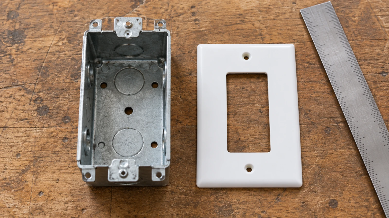
Do not choose a minimum box volume from a generic photograph. Document the conductor sizes and quantities, grounding conductors, internal clamps where applicable, and device yoke allowances. A box replacement may cost more than the device, so the survey should precede a bulk order.
| Installation condition | Evidence to obtain before ordering | Budget or approval consequence |
|---|---|---|
| Neutral not confirmed at the box | Circuit identification and a qualified site survey. | Allow for a compliant wiring change or a different installation location. |
| Box capacity uncertain | Box markings, conductor inventory, device dimensions, and a code-based fill check. | Allow for an enclosure change instead of forcing the device into place. |
| Internal supply link undocumented | The exact model’s diagram showing the required constant-power configuration. | Hold approval until the wiring arrangement is resolved. |
| Lighting load differs from switch rating | Load characteristics and the switch’s published applicable load rating. | Specify a suitable control rather than relying on receptacle amperage. |
| Installation requires additional protection | Location assessment and the applicable GFCI, AFCI, or other local protection requirements. | Include protective equipment and commissioning in the scope. |
Which standards and approvals apply to the installation?
Electrical wiring switch outlet combo decisions must start with the destination market. NFPA 70, the National Electrical Code, is an installation code used where adopted; its local edition and amendments determine requirements for the circuit, grounding, box fill, and protection. The code is not a certificate issued to a combo device. OSHA provisions cited here are US workplace requirements, not a substitute for local installation approval or a global residential wiring rule.
A receptacle rating does not automatically establish the switch’s rating for the intended lighting load. Check both functions, supply voltage and frequency, conductor compatibility, and installation conditions. Likewise, a declaration, conformity marking, or test report must be tied to the exact model and applicable market; a supplier’s general CE, RoHS, or regional compliance statement does not prove that every device is suitable for the same wiring arrangement.
If the site cannot provide the required conductors, enclosure space, grounding, or protection, stop and redesign the installation. An inexpensive device is not a saving when its selection creates a noncompliant assembly or repeated remedial visits.
How should contractors specify and buy the correct combo device?
A switch outlet combo order should be based on a documented circuit arrangement and an approved sample, not only on appearance. Four checks make the request for quotation more useful:
- Describe the constant receptacle supply and separate switched light explicitly, including the supply system and intended load.
- Request the exact model’s terminal diagram, connection instructions, conductor limits, and required tightening information.
- Confirm the switch and receptacle ratings separately, plus the applicable model-specific approvals or declarations for the destination market.
- Review a sample against the actual box, faceplate, circuit survey, and maintenance-identification requirements before releasing quantities.
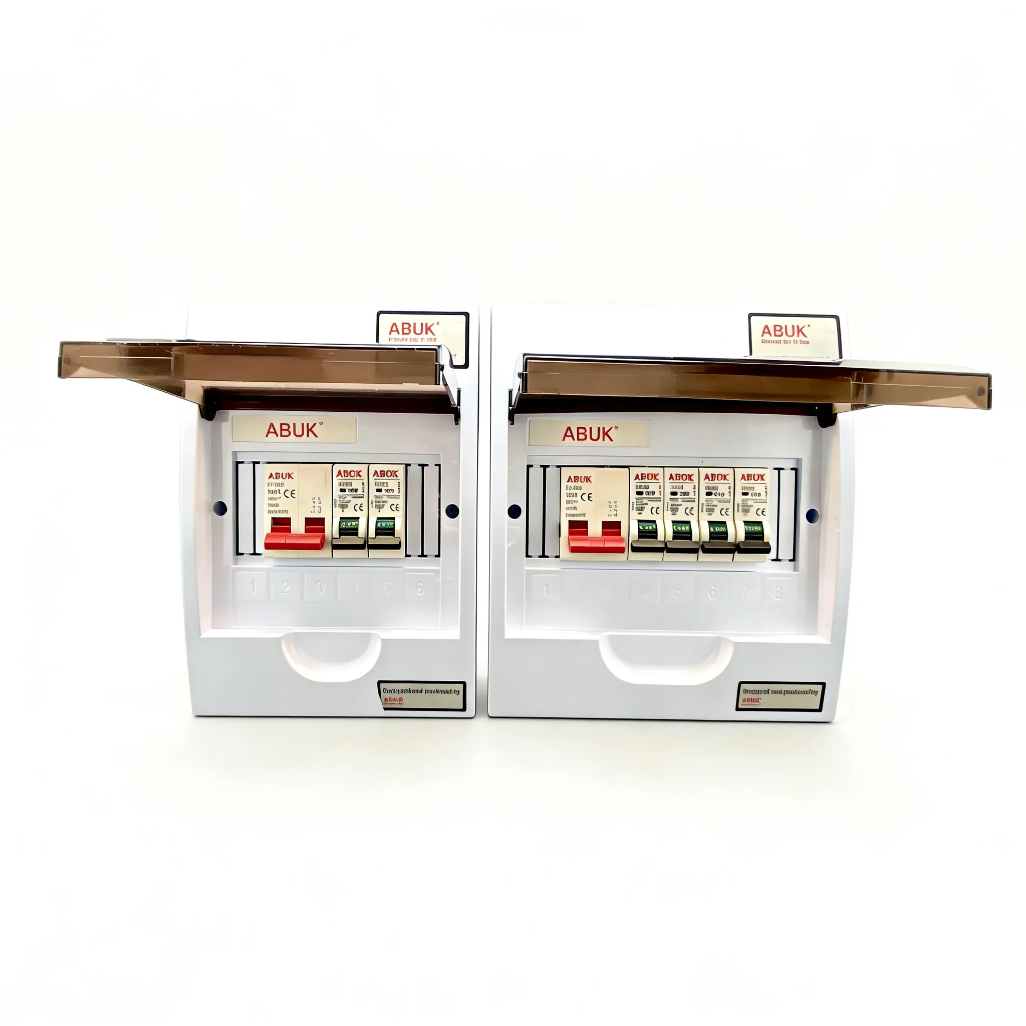
A buyer preparing a switch and outlet combo schedule can review ABUK’s S10 series catalogue and compare S08 options for a light switch outlet combo enquiry. These catalogues are starting points for a documented quotation, not proof that an individual SKU provides the topology described here. Ask for written confirmation of the exact combination device and wiring arrangement rather than assuming a switch and a socket from the same series form an interchangeable assembly.
What are the common questions about combo wiring?
How do you wire a switch outlet combo?
A qualified electrician follows the selected model’s diagram after isolating and verifying the circuit. For an always-live receptacle and a separate switched light, the required functions are constant receptacle line and neutral, switch supply and switched output, and equipment grounding. Terminal positions and internal connections are model-specific, so a generic screw-color diagram is not sufficient.
Can a combination switch and outlet share one circuit?
Yes, when the device, circuit capacity, location rules, and approved wiring arrangement permit it. In that configuration, the switch and receptacle use the same branch-circuit supply while the switch controls only its designated load. A separate-circuit design or an existing multiwire circuit requires an additional review; do not connect supplies together through a factory link.
Does a switch outlet combo need a neutral wire?
The receptacle requires the appropriate neutral for a normal line-to-neutral supply, even if the mechanical switch itself does not require neutral. Some existing switch boxes do not contain one. Equipment ground is not a substitute, and a neutral from a different circuit must not be borrowed to complete the installation.
How do I wire a combo device when the outlet is always live?
The approved arrangement keeps the receptacle connected to unswitched line and circuit neutral, while line feeds the switch and its output feeds the separate light. Retain or alter any factory link only as the exact model’s instructions specify. The installer should verify constant outlet supply in both switch positions after completing the required safety and commissioning checks.
Which references support these checks?
- OSHA 29 CFR 1910.303, General requirements: installation instructions, equipment suitability, and terminal connections.
- OSHA 29 CFR 1910.304, Wiring design and protection: conductor identification, polarity, and receptacle grounding.
- OSHA 29 CFR 1910.333, Selection and use of work practices: isolation and verification of deenergized equipment.
- NFPA 70, National Electrical Code: use the locally adopted edition, including its relevant branch-circuit and box-fill provisions.
Official source pages checked on October 8, 2026. This guide explains circuit functions and procurement checks, not an ABUK model-specific installation instruction. The supplied device instructions and the requirements of the installation jurisdiction take precedence.
What is the final decision before installation?
The decisive distinction is between an outlet that remains supplied and a load controlled by the switch. An always-live switch and outlet combo must provide those two behaviors through a documented arrangement, not an assumption about a link or terminal color. Start by confirming the circuit conductors and grounding, then select a model whose instructions support the intended connection and whose ratings suit both functions. Verify box capacity and required protection before committing to quantities. The switch’s OFF position must never be mistaken for isolation of the outlet. For procurement, ABUK’s electrical product catalogue provides a starting point for selecting a series; contact ABUK with the circuit requirements and request the exact model documentation before approving the installation.