
 Wenzhou Lita Electric Co., Ltd.


How to Wire a Switched Outlet?
A wall switch can control a plug-in lamp while the neighboring receptacle remains available for equipment that needs continuous power. The difficulty is determining whether the installed outlet supports that arrangement and whether the circuit contains separate permanent and switched live conductors. On a split-capable duplex receptacle, leaving the hot-side connecting tab intact can make both halves permanently live; removing the wrong tab can interrupt the intended neutral connection. For contractors, distributors and facilities teams, those errors can mean another site visit, replacement parts or an unusable room layout. This guide explains the common single-circuit half-hot arrangement, the role of pigtails and the checks needed before a wiring diagram becomes an installation plan.
The short answer is that a Switched Outlet receives its live supply through a suitable wall switch, while its neutral and protective grounding connections remain continuous. For a common half-hot duplex receptacle on one branch circuit, a qualified installer removes the manufacturer’s designated hot-side tab, connects permanent live to one half and switched live to the other, and normally retains the neutral-side tab. This is not a universal method for every socket. Verify the device diagram, circuit arrangement, protection and local installation rules before work. Isolate the supply and prove the conductors dead; a wall switch in the off position is not adequate isolation.
What does a wall-controlled outlet actually switch?
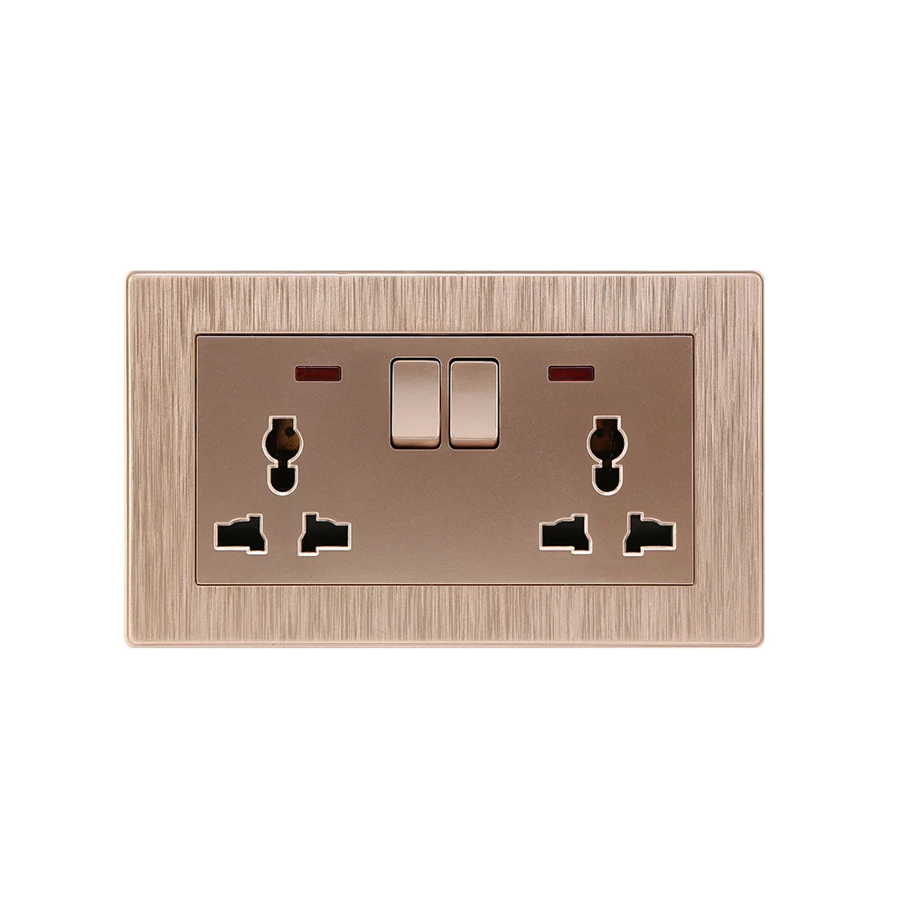
In the arrangement discussed here, the switch interrupts the live, or hot, conductor feeding the selected receptacle. The neutral completes the load circuit and the protective grounding conductor provides the required protective connection. Neither should be repurposed as a switched live conductor. A Switched Outlet does not itself identify the circuit rating, plug standard or grounding arrangement. Selecting light switches and sockets together requires checking both devices against the proposed load and circuit.

A half-hot receptacle is a duplex device whose two receptacle halves have different live feeds: one permanent and one controlled by the wall switch. Both feeds in this article come from the same branch circuit. This is different from a socket with its own built-in switch, and different again from a multiwire branch circuit that shares a neutral between separate live supplies.
The distinction matters internationally when specifying wall switches and sockets. A break-off tab is a feature of certain duplex receptacles, not a generic feature of all wall sockets. An installer working with another socket format must use its terminal markings and manufacturer instructions rather than copy a North American split-receptacle method. The HSE Electrical safety FAQs emphasize competent work and suitable precautions; a familiar-looking accessory is not evidence that its internal connections match another design.
How is a common half-hot receptacle connected?
The following explanation describes the electrical relationships for a conventional, split-capable duplex receptacle supplied by one circuit. It is not a terminal diagram for a particular product or permission to alter an existing installation without inspection. Where the circuit is unidentified, has more than one supply, or lacks a usable protective grounding arrangement, a qualified electrician must determine the correct design before proceeding.
What must be checked before touching the terminals?
First identify every supply that could energize the box, isolate and secure it against unintended re-energization, and verify absence of voltage using suitable test equipment. Existing wire colors and the position of the wall switch do not prove conductor function or safe isolation. For covered US workplaces, OSHA 29 CFR 1910.333(b) addresses de-energizing, lockout or tagging procedures and verification by a qualified person. Local electrical work requirements also apply.

How to wire a switched outlet with two wires?
First establish what the existing conductors actually do. An older two-conductor switch loop may carry a permanent live to the switch and a switched live back, with no neutral available at the switch box. It cannot provide a receptacle supply at that box merely because two insulated conductors are present. Elsewhere, a two-conductor cable may carry a switched live and neutral to a wholly switched receptacle, but not the separate permanent live needed for the half-hot arrangement described here.
A qualified electrician must trace and test the circuit after safe isolation; wire count or insulation color alone cannot establish neutral availability. If the intended location lacks the necessary conductors, an approved cable change or circuit redesign may be needed. Never substitute protective earth for a neutral or add an unrelated circuit’s neutral.
Can you run an outlet from a switch?
Only if the box has a suitable circuit supply, the necessary live, neutral and protective grounding connections, sufficient enclosure capacity and a permitted circuit arrangement. A switch box containing only a switch loop does not meet those conditions automatically. The connection sequence below applies only after those prerequisites have been verified.
- Establish the feed arrangement. The permanent live supply must feed the always-on half and the switch input. The switch output must return separately to the live terminal for the controlled half. The cable arrangement has to provide the necessary conductors; a missing return cannot be solved by using protective earth.
- Separate the hot terminals as designed. On a compatible conventional duplex receptacle, remove only the designated hot-side tab joining the two live terminals. Common devices identify this side with brass-colored terminals, but the manufacturer’s diagram and markings are decisive.
- Keep the neutral relationship correct. For the single-circuit arrangement described here, the neutral-side tab normally remains intact so both halves have the required neutral connection. The neutral is not connected to the ordinary mechanical switch’s live switching terminals.
- Maintain protective bonding. Connect the protective grounding conductors and bond the box where required. Do not remove or switch the protective grounding connection to create an additional circuit path.
- Complete and verify the assembly. Use the device’s specified conductor preparation, terminal torque and permitted termination method. After enclosure and the required electrical tests, verify that one half remains supplied and the other responds to the switch.
The half-hot receptacle depends on separating two live terminals without accidentally separating the shared neutral connection. If the hot tab remains intact, permanent live can bypass the switch and energize the nominally controlled half. If a receptacle lacks a manufacturer-designated removable tab, cutting an internal link or modifying its housing is not an equivalent procedure.
How do pigtails preserve neutral continuity?
A pigtail is a short conductor connecting a device to an approved splice. A wiring plan for wall switches and sockets should identify where splices are needed and which conductors continue downstream. Where the circuit continues through the box, the incoming and outgoing neutral conductors can be joined with a correctly rated connector and a neutral pigtail to the receptacle. In that arrangement, removing the receptacle does not require opening the through-neutral splice. Connector suitability, conductor material and size, box capacity and applicable rules must be checked.
Neutral continuity is more than a convenient service feature. An interrupted neutral can stop downstream loads from working, and a fault involving a shared neutral on a multiwire branch circuit can create additional hazards. That latter configuration is outside this article’s wiring arrangement and needs a separate assessment. Do not transfer single-circuit instructions to it merely because the receptacle has the same appearance.
Live-side pigtails can similarly distribute the permanent supply to the switch and always-on half without placing multiple conductors under a terminal that is not rated for them. Pigtails are not automatically required at every terminal, nor are two conductors automatically permitted under one screw. The device and connector instructions determine the acceptable method. Electronic switches may also require a neutral for their own operation; follow their separate diagrams rather than the simple mechanical-switch arrangement above.
Should the whole outlet or only one half be switched?
The comparison below addresses function, service implications and compatibility rather than unsupported price or performance rankings. It compares three common arrangements; final suitability depends on the actual accessory and circuit. Maintaining neutral continuity is necessary in every arrangement, although the physical connections differ.
| Arrangement | Response to the switch | Typical application | Compatibility and maintenance check |
|---|---|---|---|
| Entire duplex receptacle wall-switched | Both halves lose their live supply when switched off | Two plug-in lighting loads intended to operate together | Confirm the device diagram; a conventional intact hot-side tab may feed both halves from one switched live |
| Half-hot duplex receptacle | One half is controlled; one stays supplied | A lamp beside equipment that needs continuous power | Requires a split-capable device, separate live feeds and correct tab treatment |
| Unswitched receptacle | The wall switch does not control its supply | Equipment managed at its own controls | Confirm whether another circuit or control serves nearby lighting |
The lower-cost accessory is not necessarily the lower-cost installation. A half-hot design can need additional conductors, splicing space and commissioning checks. Conversely, making both halves switched can create service calls when equipment unexpectedly loses power. Compare total installed cost using accessory cost, cable and box changes, installation time, required testing and the likely cost of a return visit. No savings percentage is justified without project-specific labor and material evidence.
Where does switch-controlled lamp wiring make sense?
A floor or table lamp is a practical use for a Switched Outlet when room-entry control is wanted without altering the lamp. Its own switch must be left in the appropriate on position for the wall switch to control illumination. The circuit still needs suitable overcurrent protection and any additional protective measures required for that location.
| Application | Decision to make | Condition to verify | Avoidable service problem |
|---|---|---|---|
| Room-entry control of one floor lamp | Whole-outlet or half-hot supply | Lamp and switch are suitable for the connected load | Lamp appears faulty because its own switch is off |
| Lamp beside a router or charger | Provide an always-on connection separately | The selected plug position actually remains supplied | Unintended loss of power to non-lighting equipment |
| Refurbishment using existing cabling | Retain, replace or redesign the cable route | Permanent live and switched return are available where needed | Buying a split-capable receptacle before discovering missing conductors |
| Lighting with dimming or electronic control | Use a specifically permitted control and load arrangement | Manufacturer instructions and local rules permit the complete combination | Connecting general-purpose equipment to an unsuitable dimmed receptacle |
When choosing light switches and sockets for lamp control, do not assume a lighting dimmer can replace an ordinary wall switch feeding a general-purpose receptacle. A permitted dimmed receptacle arrangement can require specifically identified equipment and restrictions on connected loads. For workplace installations, the competence and safe-work principles in OSHA 1910.333 remain relevant even when the intended load is only one lamp.
Which safety and compliance checks apply?
US workplace electrical safety: OSHA 29 CFR 1910.333 establishes safety-related work practices, including provisions for de-energized equipment and qualified persons. It is not a receptacle certification or a universal residential wiring diagram. Installation requirements must also be checked against the applicable local electrical code and authority having jurisdiction.
UK electrical work: HSE’s Electrical safety FAQs cover practical safety responsibilities, competence and precautions. They do not turn a North American tab-removal technique into a suitable method for UK socket accessories. Destination-market device requirements and the installation design must be resolved independently.
European product requirements: The European Commission’s CE marking guidance explains that marking is required only where applicable EU rules require it; not every product needs CE marking. The RoHS Directive guidance addresses restrictions on specified hazardous substances in electrical and electronic equipment within its scope. Neither establishes that an accessory supports half-hot wiring.
Purchasers should match the exact model and intended market to the applicable documents rather than infer approval from a logo or a supplier’s general certificate list. An unsupported compliance claim can delay acceptance or require replacement stock; an incorrect terminal arrangement can require rework regardless of the product’s legitimate approvals.
What should buyers verify before ordering sockets and switches?
- Specify the required behavior. State whether one half, the whole receptacle or a separate socket must respond to the switch, and identify the equipment that must stay supplied.
- Request the exact wiring diagram. Confirm split capability, terminal identification, removable links, conductor limits and whether the proposed switch needs a neutral.
- Match the load and destination. Verify supply characteristics, plug format, device ratings, load type and required protective measures; a lighting application does not remove these checks.
- Check serviceability. Review available conductors, approved splices, box space and how neutral continuity will be maintained during future device replacement.
- Agree the handover checks. Require appropriate electrical testing, confirmation of the switched and permanent outputs, and a record of the installed arrangement.
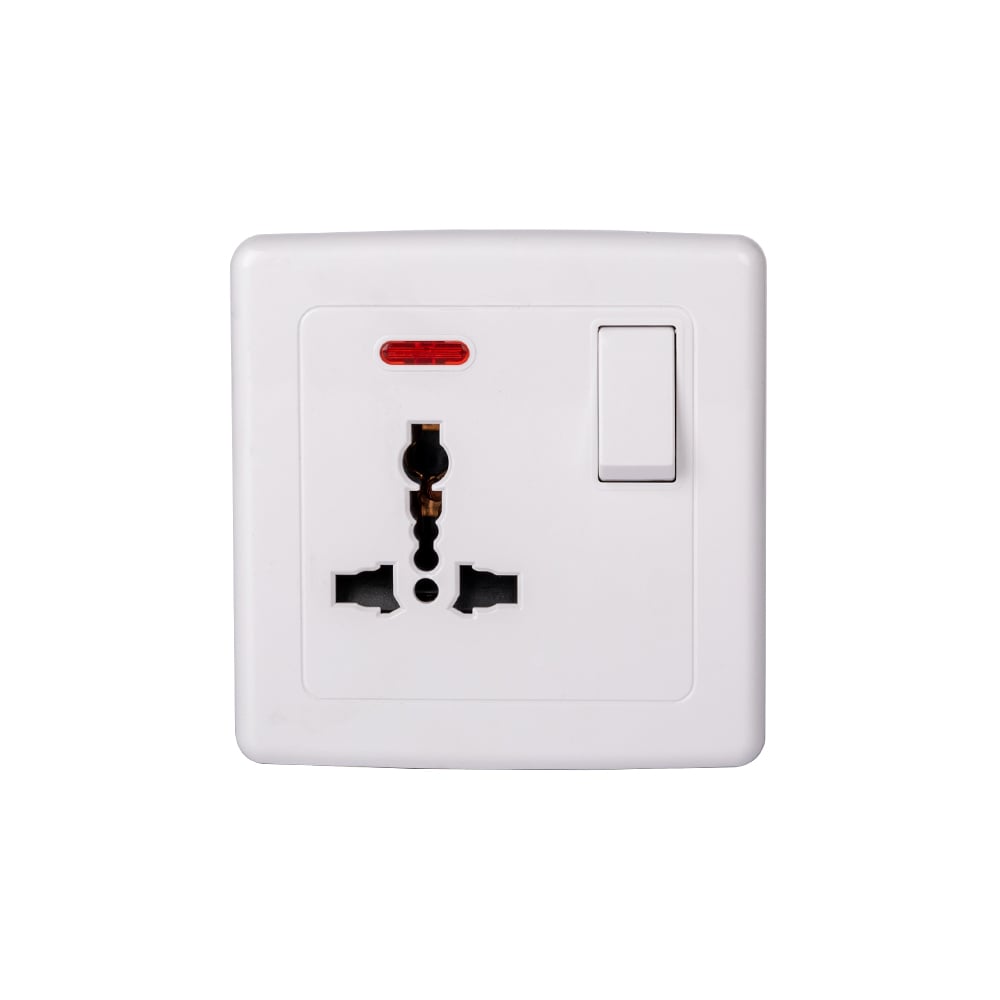
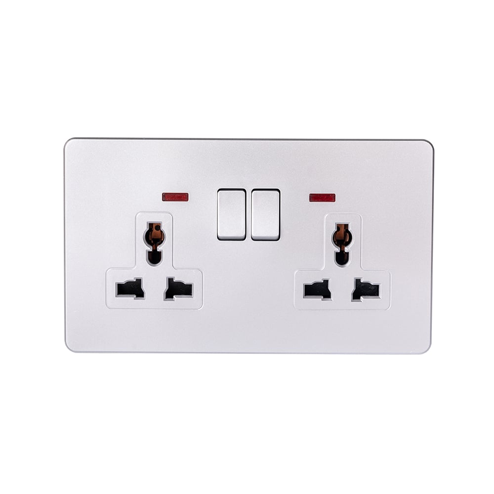
For an ABUK sourcing discussion, the S10 wall switches and sockets and S08 light switches and sockets pages provide relevant starting points for comparing ranges. Their inclusion does not assert that every listed socket supports split wiring. Ask for the exact model’s terminal diagram and destination-market documentation before specifying a half-hot configuration.
What are the frequently asked questions?
How do you wire a switched outlet?
A Switched Outlet normally receives live power through a suitable switch, with its neutral and protective grounding connections maintained. For a half-hot duplex device, permanent and switched live feeds serve separate halves after the manufacturer-designated hot tab is removed. A qualified installer must confirm the device diagram, circuit identity, local rules and safe isolation before making connections.
Can one half of an outlet be controlled by a switch?
Yes, when the duplex receptacle is designed for split operation and the circuit provides the correct conductors. A half-hot receptacle can leave one half permanently supplied while the switch controls the other. Do not assume a different socket format, protected receptacle or electronic accessory can be modified the same way.
Which tab is removed for a half-switched receptacle?
In the common single-circuit split duplex arrangement, remove the designated hot-side tab, usually between the brass-colored live terminals. The neutral-side tab normally remains intact for that configuration. Follow the manufacturer’s markings and diagram; the rule must not be applied blindly to a different device or multiwire circuit.
What is the difference between a switched and unswitched socket?
A switched socket has a switch controlling its power supply, either built into the accessory or located separately. An unswitched socket stays supplied while its circuit is energized, although the connected appliance may have its own controls. Neither description proves that the socket is safe to work on; supply isolation and absence-of-voltage verification remain necessary.
Which official references support these checks?
- OSHA, 29 CFR 1910.333: Selection and use of work practices – US workplace electrical safety and de-energization requirements.
- HSE, Electrical safety FAQs – competence, precautions and practical electrical safety guidance.
- European Commission, CE marking – applicability and manufacturer responsibilities.
- European Commission, RoHS Directive – hazardous-substance restrictions and regulatory scope.
Sources and comparison framework reviewed on October 8, 2026. The tables compare circuit behavior and verification needs, not measured product performance. ABUK is the commercial publisher; no project results, prices or model-specific split-wiring approvals are asserted.
What is the final decision rule?
The important distinction is not whether a socket has a switch nearby, but whether the correct live path is controlled while neutral and protective grounding connections remain intact. First decide what must turn off and what must stay supplied. Then identify the circuit, verify the available conductors and select a device whose manufacturer permits the proposed arrangement. Only after those checks should tab removal, pigtails and termination details be specified. Do not skip safe isolation or electrical verification because the load is a small lamp. A suitable accessory cannot compensate for an incorrectly understood circuit. For ABUK procurement, review the sockets and switches catalog and contact the team with the intended market, load and required switching behavior to request the relevant model documentation.