
 Wenzhou Lita Electric Co., Ltd.


How to Wire a Single Pole Light Switch Using a 3-Way Switch
When a technical engineer in Norway encountered a broken switch during a commercial facility upgrade deep in a remote fjord, waiting days for a replacement part was simply not an option. Needing to restore critical lighting immediately, the engineer grabbed the only spare component available on-site: a three-way switch. Assuming the wiring would be a straightforward, color-matched swap, they blindly connected the incoming hot wire to one of the traveler terminals. The result? The moment the power was restored, the breaker tripped instantly, halting the entire project and nearly causing the facility to fail a strict local electrical safety audit. The issue was not a defective product; rather, it was a fundamental misunderstanding of the internal circuit logic and terminal definitions of the hardware.
Summary: Yes, you can safely and effectively wire a single pole light switch using a 3-way switch. The core solution lies in identifying the “Common” terminal for the incoming hot wire, connecting the load wire to just one of the “Traveler” terminals, and securely capping the unused traveler terminal with a wire nut. Grounding remains mandatory.In commercial and industrial projects, supply chain delays or strict inventory limitations often force contractors to adapt on the fly. While substituting a three-way switch for a single pole switch is electrically sound, improper execution carries severe risks. According to the Electrical Safety Foundation International (ESFI), electrical malfunctions account for thousands of commercial fires annually, many stemming from improper terminal connections and overloaded circuits. Understanding the internal mechanics of these devices is non-negotiable for operational safety.
Anatomy of a Single Pole vs. 3-Way Switch
To understand why the Norwegian engineer’s breaker tripped, we must dissect the mechanical differences between these two common light switches.
A standard single pole switch is a simple “make or break” mechanism. It features two brass terminals (one for the incoming line/hot wire, and one for the outgoing load wire to the light fixture) and one green grounding screw. When the toggle is flipped, it either connects or severs the circuit.
A 3 way switch, however, is designed to control a single fixture from two different locations. Therefore, it does not have a definitive “on” or “off” position. Instead, it features three active terminals plus a ground. The Common Terminal is usually identified by a black or darker-colored screw, acting as the critical entry or exit point for the electrical current. The Traveler Terminals consist of two brass or lighter-colored screws that provide two alternate paths for the current to travel to the secondary switch. Finally, the Ground Terminal is a green screw dedicated to the bare copper or green grounding wire.
Step-by-Step Wiring Guide
When you use a three-way switch in a single-pole application, you are essentially ignoring one of the alternate paths, forcing the switch to act as a simple interrupter. We recommend following these precise steps, adhering to IEC 60669 standards for fixed electrical installations:
Step 1: Disconnect and Verify Power. Always turn off the power at the main circuit breaker. Use a reliable digital multimeter to verify that the voltage across the wires is at absolute zero before proceeding.
Step 2: Identify the Common Terminal. Locate the dark-colored screw on the new switch. This is where your incoming hot wire (usually black, carrying 120V or 240V depending on your region) must be connected.
Step 3: Connect the Hot and Load Wires. Attach the incoming power wire to the Common terminal. Next, attach the outgoing load wire (the wire leading to the light fixture) to either one of the two brass Traveler terminals.
Step 4: Secure the Unused Terminal. You will have one brass Traveler terminal left empty. It is an industry best practice to tighten this screw down and, if necessary, wrap the switch body in electrical tape to prevent accidental arcing.
Step 5: Ground the Circuit. Connect the bare copper or green wire to the green grounding screw. Never skip this step; it is a mandatory safety requirement under the National Electrical Code (NEC) for handling fault currents (typically rated for 15A or 20A circuits).
Terminal Comparison: Single Pole vs. 3-Way Switch
To lower the cognitive load during field installations, the following table outlines the critical differences in terminal configurations.
| Feature / Dimension | Single Pole Switch | 3-Way Switch | Application Note |
|---|---|---|---|
| Terminal Count | 2 (Line, Load) | 3 (Common, Traveler 1, Traveler 2) | 3-way requires capping one traveler for single-pole use. |
| Common Screw Color | N/A (Both are brass) | Black or Dark Oxidized | Critical for identifying the primary power input. |
| Traveler Screws | None | 2 (Brass / Gold) | Provides alternate current paths; only one is used here. |
| Grounding Requirement | Mandatory (Green Screw) | Mandatory (Green Screw) | Essential for safety compliance across all regions. |
| Typical Application | Controlling one light from one location | Controlling one light from two locations | Can be retrofitted downward, but not upward. |
The Hidden Costs of Improper Wiring and Substandard Components
When contractors improvise wiring without understanding the underlying mechanics, the hidden costs escalate rapidly. A miswired switch might seem functional initially, but if the load is incorrectly distributed or if the internal contacts of the switch are of poor quality, it increases the Total Cost of Ownership (TCO) for the facility.
Using low-grade mechanical wall switches in commercial environments leads to premature contact wear, micro-arcing, and eventual thermal failure. In a large-scale deployment, a 5% failure rate due to substandard components or improper installation can result in thousands of dollars in maintenance call-outs and operational downtime. High-quality switches utilize silver-alloy contacts to mitigate arcing and ensure a lifespan exceeding 40,000 actuations.
Navigating Electrical Standards and Compliance
An electrical installation that fails to comply with international standards is a massive liability. Non-compliance can lead to catastrophic hardware failure, electrocution, and the immediate voiding of commercial property insurance policies.
IEC 60669: This is the primary international standard for switches for household and similar fixed-electrical installations. It dictates the mechanical endurance, temperature rise limits, and dielectric strength required for safe operation.
CE & RoHS: In the European Economic Area, CE marking ensures the product meets health, safety, and environmental protection standards. RoHS compliance guarantees the absence of hazardous materials like lead and cadmium in the switch’s manufacturing.
GCC (Gulf Conformity Mark): For projects in the Middle East, this certification is mandatory to prove that low-voltage electrical equipment can withstand extreme regional temperatures and voltage fluctuations.
Practical Pitfalls and Procurement Guidelines
For project managers and technical engineers, avoiding electrical failures requires both precise execution and strategic procurement. Here are the critical guidelines to ensure your installation remains safe and compliant:
1. Always Use a Multimeter: Never trust wire colors alone, especially in older commercial buildings. Always use a multimeter to definitively identify the incoming hot wire before connecting it to the Common terminal.
2. Do Not Ignore the Ground: A missing ground connection will not stop the light from working, but it removes the only safe path for fault currents, creating a severe shock hazard.
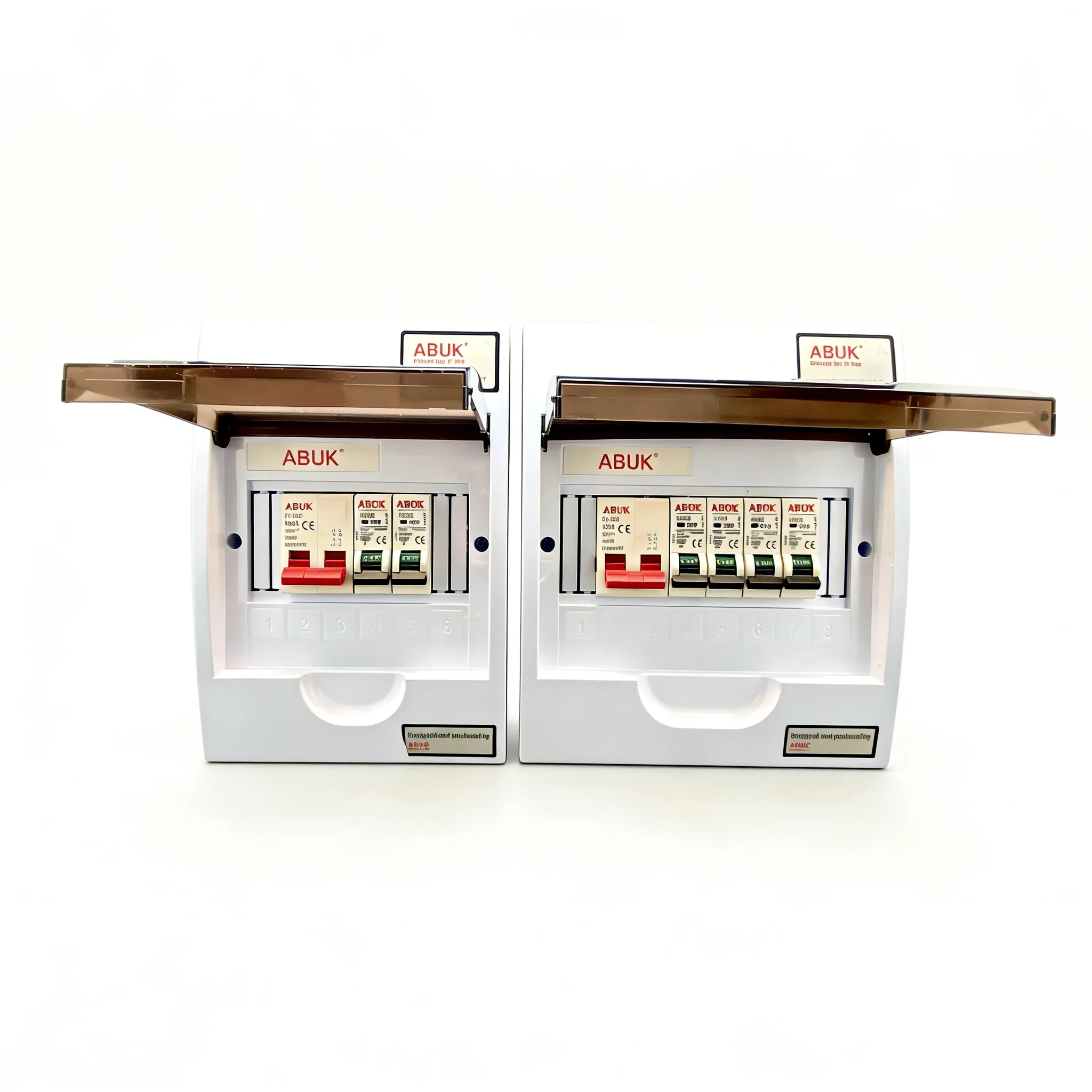
3. Standardize Your Procurement: Mixing and matching cheap components leads to inconsistent installations. Source your electrical hardware from manufacturers that adhere to strict global testing protocols. ABUK provides mechanical wall switches, distribution boards, and related electrical products with rigorous CE, RoHS, and GCC certifications. Engineered for high-endurance commercial environments, these components ensure that even when field engineers must adapt on the fly, the underlying hardware guarantees safety and compliance.
Frequently Asked Questions
Can you use a single pole switch with a 3-way switch?
In a standard 3-way circuit designed to control one light from two different locations, you cannot use a standard single pole switch. A single pole switch lacks the necessary traveler terminals to pass the electrical current back and forth between the two switch locations. You must use two 3-way switches.
How to wire a 3 way light switch to a single pole outlet?
If you are using a 3-way switch to control a standard single-pole switched receptacle (outlet), connect the incoming hot wire to the Common terminal on the switch. Then, connect the wire leading to the outlet to one of the Traveler terminals. Ensure you securely cap the unused traveler terminal with a wire nut.
Does it matter which wire goes where on a 3-way light switch?
Yes, absolutely. The incoming power wire (or the outgoing load wire to the fixture) must connect to the Common terminal (usually the black screw). The two traveler wires must connect to the two brass traveler terminals. Reversing the common and a traveler will cause the circuit to fail or trip the breaker.
Is a 3 way light switch a single pole double throw?
Yes. In electrical engineering terms, a standard 3-way light switch is classified as a Single Pole Double Throw (SPDT) switch. It has one input (the pole/common) and two possible outputs (the throws/travelers), allowing current to be directed down one of two alternate paths.
What are the common mistakes when wiring a 3-way switch?
The most frequent errors include misidentifying the common wire (often confusing it with a traveler based purely on wire color), failing to properly cap unused traveler terminals when used in single-pole applications, and neglecting the ground wire connection, which violates NEC and IEC safety standards.
What is the difference between single pole and single pole double throw switches?
A standard single pole switch (Single Pole Single Throw, or SPST) simply opens or closes one single circuit path. A single pole double throw (SPDT) switch, such as a 3-way switch, routes the incoming current from one common input to one of two separate output paths.
{
“@context”: “https://schema.org”,
“@type”: “FAQPage”,
“mainEntity”: [
{
“@type”: “Question”,
“name”: “Can you use a single pole switch with a 3-way switch?”,
“acceptedAnswer”: {
“@type”: “Answer”,
“text”: “In a standard 3-way circuit designed to control one light from two different locations, you cannot use a standard single pole switch. A single pole switch lacks the necessary traveler terminals to pass the electrical current back and forth between the two switch locations. You must use two 3-way switches.”
}
},
{
“@type”: “Question”,
“name”: “How to wire a 3 way light switch to a single pole outlet?”,
“acceptedAnswer”: {
“@type”: “Answer”,
“text”: “If you are using a 3-way switch to control a standard single-pole switched receptacle (outlet), connect the incoming hot wire to the Common terminal on the switch. Then, connect the wire leading to the outlet to one of the Traveler terminals. Ensure you securely cap the unused traveler terminal with a wire nut.”
}
},
{
“@type”: “Question”,
“name”: “Does it matter which wire goes where on a 3-way light switch?”,
“acceptedAnswer”: {
“@type”: “Answer”,
“text”: “Yes, absolutely. The incoming power wire (or the outgoing load wire to the fixture) must connect to the Common terminal (usually the black screw). The two traveler wires must connect to the two brass traveler terminals. Reversing the common and a traveler will cause the circuit to fail or trip the breaker.”
}
},
{
“@type”: “Question”,
“name”: “Is a 3 way light switch a single pole double throw?”,
“acceptedAnswer”: {
“@type”: “Answer”,
“text”: “Yes. In electrical engineering terms, a standard 3-way light switch is classified as a Single Pole Double Throw (SPDT) switch. It has one input (the pole/common) and two possible outputs (the throws/travelers), allowing current to be directed down one of two alternate paths.”
}
},
{
“@type”: “Question”,
“name”: “What are the common mistakes when wiring a 3-way switch?”,
“acceptedAnswer”: {
“@type”: “Answer”,
“text”: “The most frequent errors include misidentifying the common wire (often confusing it with a traveler based purely on wire color), failing to properly cap unused traveler terminals when used in single-pole applications, and neglecting the ground wire connection, which violates NEC and IEC safety standards.”
}
},
{
“@type”: “Question”,
“name”: “What is the difference between single pole and single pole double throw switches?”,
“acceptedAnswer”: {
“@type”: “Answer”,
“text”: “A standard single pole switch (Single Pole Single Throw, or SPST) simply opens or closes one single circuit path. A single pole double throw (SPDT) switch, such as a 3-way switch, routes the incoming current from one common input to one of two separate output paths.”
}
}
]
}
References
- Electrical Safety Foundation International (ESFI): Workplace Safety
- International Electrotechnical Commission (IEC): IEC 60669 Standards
- National Fire Protection Association (NFPA): National Electrical Code (NEC)
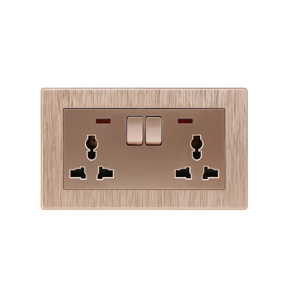
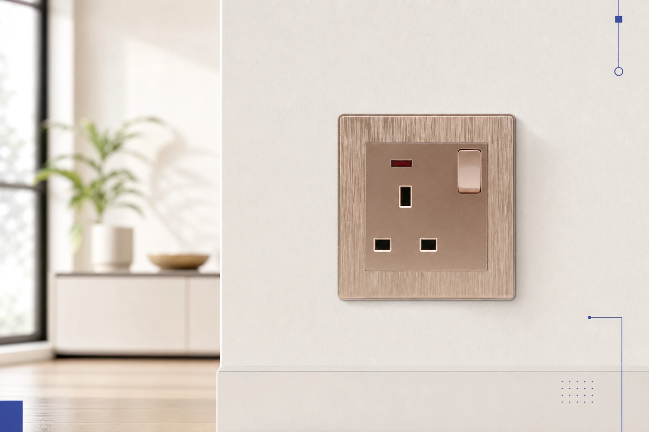
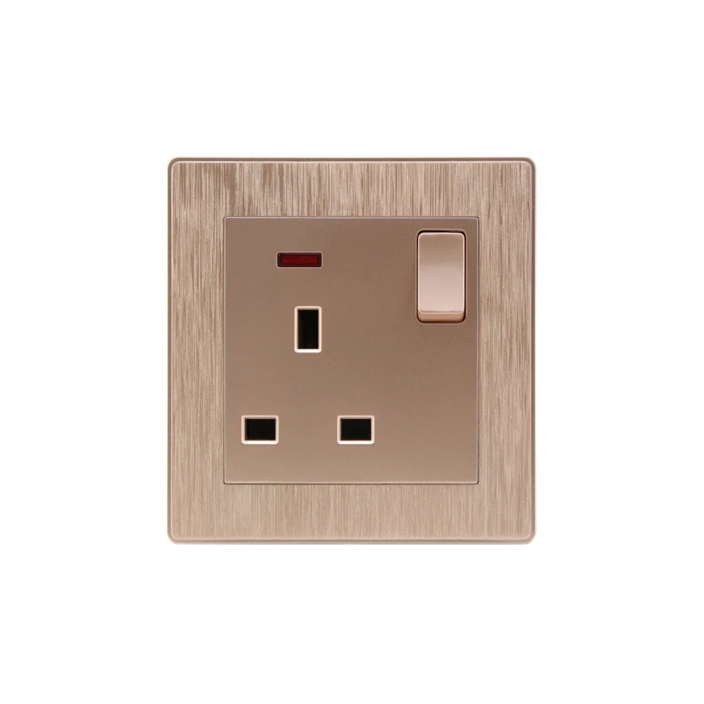
After consulting on hundreds of commercial electrical retrofits, the most valuable lesson we’ve learned from the field is this: improvisation is inevitable, but compromising on component quality is unforgivable. When a technician is forced to use a 3-way switch in a single-pole setup to meet a tight deadline, the success of that workaround relies entirely on their understanding of the circuit and the durability of the hardware. The difference between a safe electrical installation and a hazardous failure is not just in the wires you connect—it is in the quality of the components and the standards you uphold. ABUK builds mechanical wall switches and distribution boards grounded in this exact field-tested reality, ensuring that even when your team must adapt on the fly, the hardware never compromises on safety. Explore our certified commercial solutions at ABUK 13A Single Switched Socket Series and equip your projects with hardware you can trust.