
 Wenzhou Lita Electric Co., Ltd.
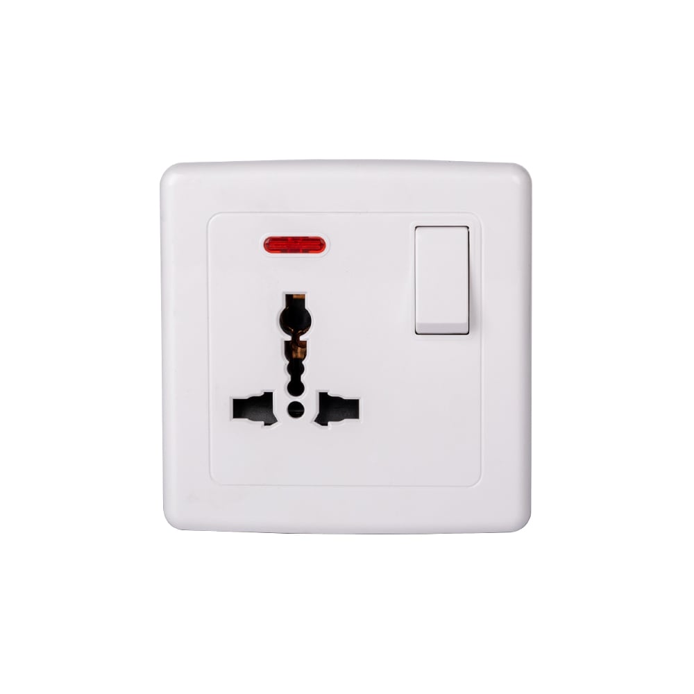
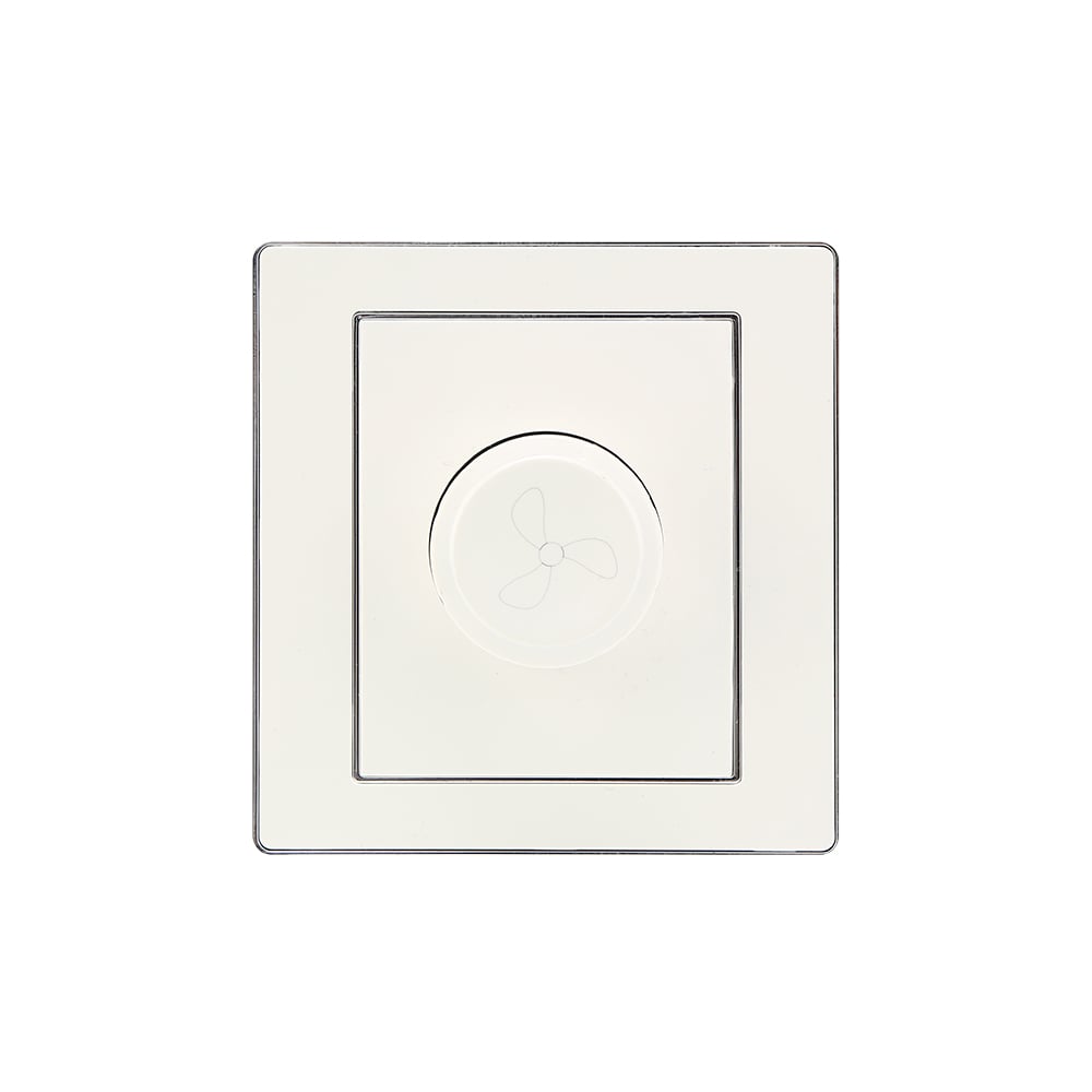
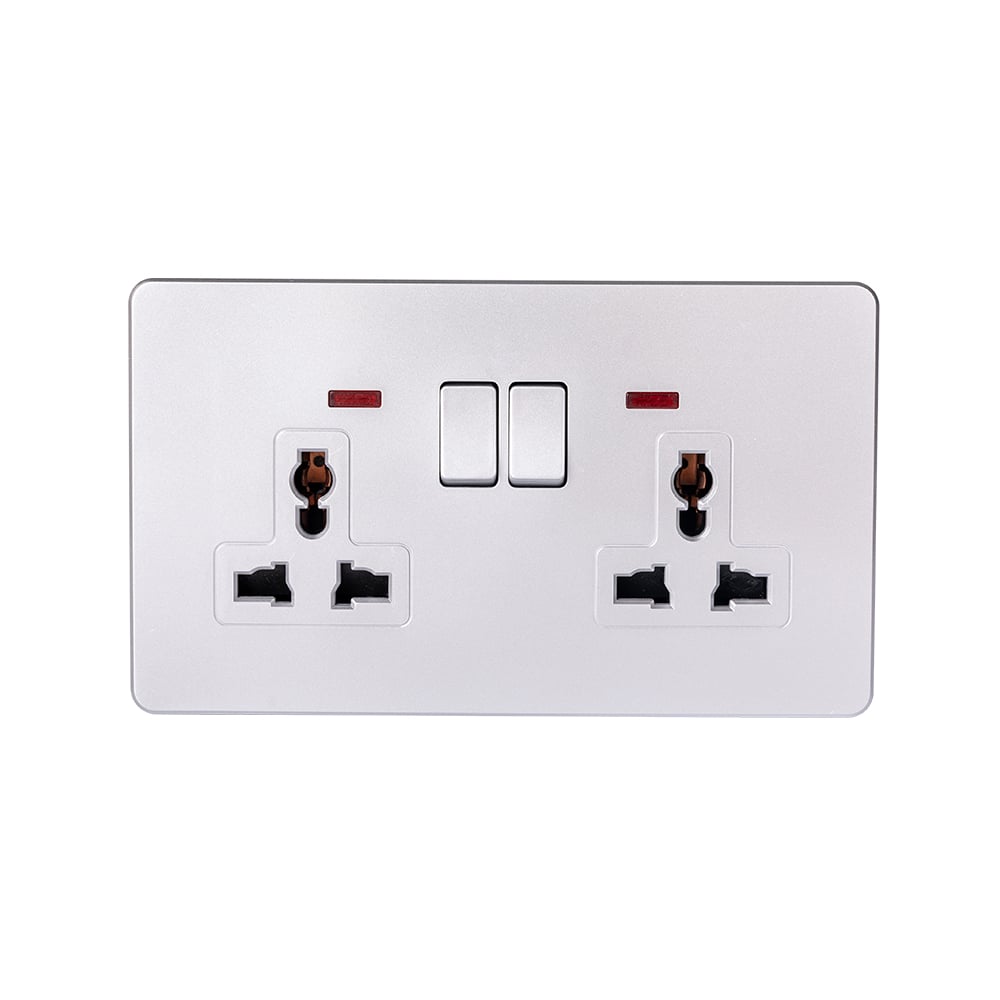
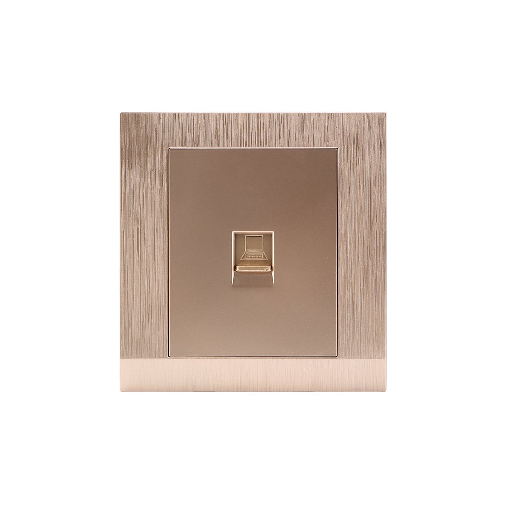



Wall Switches Installation and Wiring
Summary: Correct wall switch wiring depends on three fundamentals: load rating, switching function, and compliance with local electrical standards. A single-pole switch, 2-way circuit, 3-way circuit, timer switch, or double switch may look similar from the outside, but each has different wiring logic and failure risks. For B2B buyers, the honest answer is this: installation quality is not only an electrician’s issue; it directly affects warranty claims, project acceptance, safety compliance, and total cost of ownership. Use certified products, verify diagrams before installation, and match each switch type to the real site load and regulatory market.

What Does Wall Switch Wiring Actually Involve?
A wall switch is a control device used to open or close an electrical circuit, usually for lighting, fans, small appliances, or auxiliary building systems. In simple terms, it interrupts the live conductor, not the neutral conductor; this is a basic safety principle recognized in many wiring practices aligned with IEC-based electrical systems.
In most low-voltage building applications, switch circuits operate at common rated voltages such as 220–240V AC in many IEC markets or 110–120V AC in North American-style systems. Current ratings commonly include 10A, 13A, 16A, or 20A, depending on the product design and local standard.In electrical product procurement, poor electric wall switch wiring can create hidden costs: repeated callouts, wall repair, delayed commissioning, rejected inspection, warranty disputes, and distributor complaints.
How Does a Basic Wall Switch Circuit Work?
A basic mechanical switch controls the live line of a circuit. When the switch is ON, the circuit closes and current flows to the load; when OFF, the circuit opens and the load is isolated from the live supply.
A typical single-pole switch circuit includes:
- Live input / line conductor
- Switched live output
- Load, such as a lamp or fan
- Neutral conductor, usually connected directly to the load
- Earth / protective conductor, where required by the system
A simple wall switch wiring diagram normally shows one live feed entering the switch and one switched live leaving toward the fixture. In many IEC-oriented installations, color coding may follow regional rules, but older buildings may not follow current color conventions. That is why the conductor should be verified with proper testing equipment before connection.
From a standards perspective, IEC-based wiring practice emphasizes proper isolation, conductor sizing, enclosure suitability, and protection against electric shock. For product compliance, CE marking indicates conformity with applicable EU safety, health, and environmental requirements, while RoHS restricts hazardous substances in electrical and electronic products.
Practical Technical Numbers
| Parameter | Common Value | Why It Matters |
|---|---|---|
| Rated voltage | 220–240V AC or 110–120V AC | Must match destination market |
| Rated current | 10A / 13A / 16A / 20A | Prevents overheating and contact damage |
| Contact endurance | Often thousands of operations | Affects lifecycle and replacement cost |
| Conductor size | Commonly 1.0–2.5 mm² depending on circuit | Must match load and local code |
| Mounting depth | Often 35–47 mm wall box depth | Affects fit and installation speed |
The ROI logic is straightforward: a properly selected switch costs slightly more at procurement stage, but it reduces rework, warranty claims, and project delay risk.
How Is 2 Way Wall Switch Wiring Different?
2 way wall switch wiring allows one lighting circuit to be controlled from two different locations. This is common in staircases, corridors, hotel rooms, warehouses, and large residential spaces.
A 2-way circuit usually uses:
- One common terminal on each switch
- Two traveler conductors between switches
- One switched live output to the load
In IEC terminology, this is often called two-way switching. In some markets, similar switching functions may be described differently, so the wiring diagram must be checked against local terminology.
A practical example: in a hotel corridor, the user may need to turn the light ON at one entrance and OFF at the other end. If the traveler wires are reversed or the common terminal is misidentified, the switch may behave unpredictably, or the light may only work in one switch position.
A standard 2-way circuit generally requires three active conductors between functional points: one common path and two travelers, depending on installation method. This increases wiring complexity compared with a single-pole circuit.
For contractors, the hidden cost is labor. If a finished wall must be reopened because the traveler conductors were not planned, the cost is not the switch price; it is labor, plastering, painting, and project delay.
How Does 3 Way Wall Switch Wiring Work?
In many North American contexts, 3 way wall switch wiring refers to controlling one load from two locations. In many IEC-influenced markets, this may be called 2-way switching. This terminology mismatch is one of the most common causes of procurement and installation confusion in cross-border projects.
For international B2B buyers, we recommend treating “3-way” as a market-specific term rather than assuming universal meaning. A buyer should always confirm:
- Destination country
- Wiring convention
- Terminal marking
- Load type
- Product rating
- Installation diagram
In North American-style systems, 3-way switch circuits often use two 3-way switches and traveler wires. The nominal voltage is commonly 120V AC, while many IEC markets use 230V AC. This difference matters because insulation design, marking, and certification expectations vary.
The project lesson is simple: do not purchase based only on product appearance. A switch plate may look correct, but the internal contact arrangement and terminal marking determine whether it is suitable for the wiring method.
What Should Buyers Know About Double and Dual Wall Switch Wiring?
Double wall switch wiring and dual wall switch wiring usually refer to two switching functions integrated into one wall plate or one switch module assembly. This is common where one panel controls two loads, such as:
- Main light + decorative light
- Fan + light
- Indoor light + outdoor light
- Two lighting zones in one room
A double switch saves wall space and improves user convenience, but it also increases wiring density inside the back box. If the mounting box is shallow, conductors may be compressed, causing poor termination, heat buildup, or difficulty during maintenance.
Typical Technical Considerations
| Item | Single Switch | Double / Dual Switch |
|---|---|---|
| Number of controlled loads | 1 | 2 |
| Wiring complexity | Low | Medium |
| Back box space demand | Lower | Higher |
| Miswiring risk | Lower | Higher |
| Inspection importance | Standard | Higher |
If each switch gang is rated at 10A, that does not always mean the assembly should be treated casually under all load conditions. Heat dissipation, conductor bending radius, and enclosure space still matter.
For distribution projects, poor documentation around double switches can lead to distributor complaints because installers may expect one wiring layout but receive another. Clear datasheets, terminal labels, and diagrams reduce this risk.
How Do Wall Timer Switches Change Installation Requirements?
Wall timer switches introduce timing control into a circuit. They may be used for stairwell lighting, bathroom fans, outdoor lighting, energy-saving projects, or small commercial facilities.
Unlike a simple mechanical switch, wall timer switches may require:
- Live input
- Load output
- Neutral connection, depending on design
- Minimum load compatibility
- Time range setting
- Load type confirmation
Common timer ranges may include 30 seconds to 30 minutes, or longer depending on product type. Some electronic timer switches need a neutral wire to power the timing circuit. If the wall box has only live and switched live conductors, the timer may not function unless the model supports no-neutral installation.
This is a typical hidden-cost problem. A buyer may select a timer switch to reduce energy consumption, but if the existing wiring lacks neutral, the site may require additional wiring work. The ROI should include both product cost and installation cost.
Wall Switch Wiring Options Compared
| Wiring Type | Typical Use | Installation Complexity | Key Risk | Cost Impact | TCO Consideration |
|---|---|---|---|---|---|
| Single-pole wall switch | One switch controls one load | Low | Live/neutral confusion | Low | Lowest maintenance burden |
| 2 way wall switch wiring | Two locations control one light | Medium | Traveler/common misconnection | Medium | Good for corridors and stairs |
| 3 way wall switch wiring | Market-specific two-location control term | Medium | Terminology mismatch | Medium | Requires market-specific diagram |
| Double wall switch wiring | Two loads in one plate | Medium | Crowded back box | Medium | Saves space but needs careful planning |
| Dual wall switch wiring | Two independent functions | Medium | Load separation error | Medium | Useful for multi-zone rooms |
| Wall timer switches | Timed lighting or fan control | Medium–High | Neutral requirement or load mismatch | Medium–High | Can reduce energy waste if correctly selected |
| Switch 2 wall mount setup | Two wall-mounted switching points or two-gang arrangement | Medium | Incorrect box depth or module fit | Medium | Needs clear mounting and wiring planning |
A switch 2 wall mount arrangement should be clarified during procurement because suppliers, contractors, and installers may use the phrase differently. It may mean two switches mounted on a wall, a two-gang wall plate, or a two-location switching setup. Ambiguity creates cost.
Application Matrix for Wall Switch Selection
| Application Scenario | Suitable Switch Type | Common Load | Wiring Complexity | Procurement Focus |
|---|---|---|---|---|
| Residential bedroom | Single or dual switch | LED lighting | Low–Medium | Appearance, rating, durability |
| Hotel corridor | 2-way / timer switch | Corridor lighting | Medium | Wiring diagram, endurance, compliance |
| Commercial office | Double switch | Lighting zones | Medium | Modularity, plate finish, easy maintenance |
| Warehouse aisle | 2-way or timer switch | Industrial lighting | Medium–High | Current rating, enclosure robustness |
| Bathroom fan control | Timer switch | Fan motor | Medium | Neutral requirement, inductive load rating |
| GCC market projects | CE/RoHS/GCC-compliant switch | Lighting and small loads | Medium | Certification documents, Arabic/English packaging if needed |
| Distributor inventory | Standard mechanical ranges | Mixed applications | Medium | SKU clarity, stable supply, documentation |
This table matters because B2B purchasing is not only about unit price. The right specification reduces slow-moving inventory, installer confusion, and after-sales disputes.
Standards and Compliance: Why Certification Still Matters
For international B2B procurement, wall switches should not be evaluated only by appearance, price, or basic electrical rating; certification support is part of the product’s commercial usability. Products with CE, RoHS, and GCC compliance documentation are easier to specify for export projects, distributor channels, and regulated construction markets because they help prove that the product has been designed and supplied with safety, material restriction, and regional conformity requirements in mind. The business risk of ignoring certification is rarely limited to the switch itself — it may lead to customs delays, failed project inspections, rejected submittals, warranty disputes, distributor complaints, or even safety-liability exposure after installation.
Selection Guide: How to Avoid Common Wall Switch Wiring Mistakes
1. Confirm the Switching Function Before Buying
Do not buy a product only because the front plate looks correct. Confirm whether the project needs a single-pole switch, 2-way switch, double switch, timer switch, or market-specific 3-way function.
2. Match Current Rating to the Real Load
A switch used for LED lighting, fan motors, or mixed loads may face different inrush and operating conditions. A 10A rating may be sufficient for many lighting circuits, but the load profile should still be checked.
3. Check the Wall Box Depth and Wiring Space
Crowded wiring creates installation stress. For double or dual switches, deeper boxes often improve termination quality and future maintenance.
4. Ask for a Clear Wiring Diagram
A proper wall switch wiring diagram reduces installer errors, especially for distributors selling into multiple regions. Diagrams should identify line, load, common, traveler, and neutral requirements where applicable.
5. Choose Certified Product Families for Export Projects
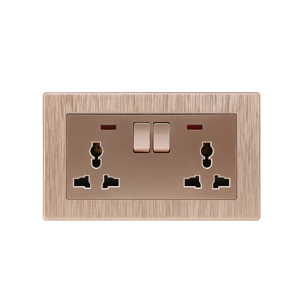
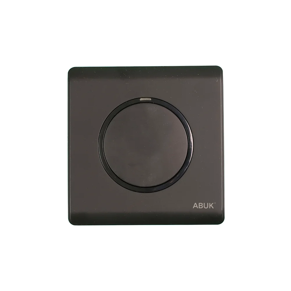
ABUK provides mechanical wall switches, wall switch socket solutions, and related electrical products with CE, RoHS, and GCC certification support for B2B buyers who need consistent documentation, export-ready product ranges, and practical installation compatibility.
FAQs
How do you wire a basic wall switch?
A basic wall switch wiring method connects the live input to the switch and the switched live output to the load. The neutral usually goes directly to the load. Always isolate power first, verify the conductor with a tester, and follow the local electrical code before installation.
What is the difference between 2 way and 3 way wall switch wiring?
The difference is often terminology. In many IEC markets, 2 way wall switch wiring means one light controlled from two locations. In North America, 3 way wall switch wiring often describes a similar function. For export projects, the safest approach is to confirm the destination market, terminal marking, and wiring diagram before procurement.
How to install wall paneling around outlets and switches?
To install wall paneling around outlets and switches, power should be isolated first, then the outlet or wall switch cover plate should be removed. The panel opening must be measured and cut accurately so the device sits flush with the finished surface. For commercial projects, we recommend confirming box extender requirements and local code rules before closing the wall.
How to install a ceiling fan wall switch?
To install a ceiling fan wall switch, identify whether the fan requires single-speed control, multi-speed control, or separate light and fan control. The live conductor, switched output, neutral, and earth connection should be verified before wiring. Fan loads may behave differently from lighting loads, so the switch rating and load compatibility should be checked carefully.
How to install a timer on a wall switch?
To install a timer on a wall switch, first check whether the timer model requires a neutral wire. Many wall timer switches need live, load, and neutral connections to power the timing circuit. If the existing box has only live and switched live wires, a no-neutral timer model or additional wiring work may be required.
How to install a wall light switch?
To install a wall light switch, turn off the circuit breaker, verify that the circuit is not energized, connect the live input to the switch common terminal, and connect the switched live to the lighting load. The neutral usually remains connected to the light fitting, not the switch. After installation, test the switch operation before refitting the cover plate.
What should be checked before electric wall switch wiring?
Before electric wall switch wiring, check the supply voltage, rated current, load type, terminal markings, conductor size, wall box depth, and applicable local electrical requirements. A clear wall switch wiring diagram helps reduce miswiring, especially in multi-market B2B projects.
References
- International Electrotechnical Commission IEC — International standards for electrical and electronic technologies
https://www.iec.ch/ - European Commission — CE Marking
https://single-market-economy.ec.europa.eu/single-market/ce-marking_en - European Commission — RoHS Directive
https://environment.ec.europa.eu/topics/waste-and-recycling/rohs-directive_en - GCC Standardization Organization GSO
https://www.gso.org.sa/ - NFPA 70 National Electrical Code overview
https://www.nfpa.org/
A wall switch is often one of the smallest components in a building project, but it can decide whether the installation feels professional, passes inspection smoothly, and remains reliable after handover. The best wiring outcome comes from a simple discipline: understand the circuit before choosing the product, and verify the product before closing the wall.
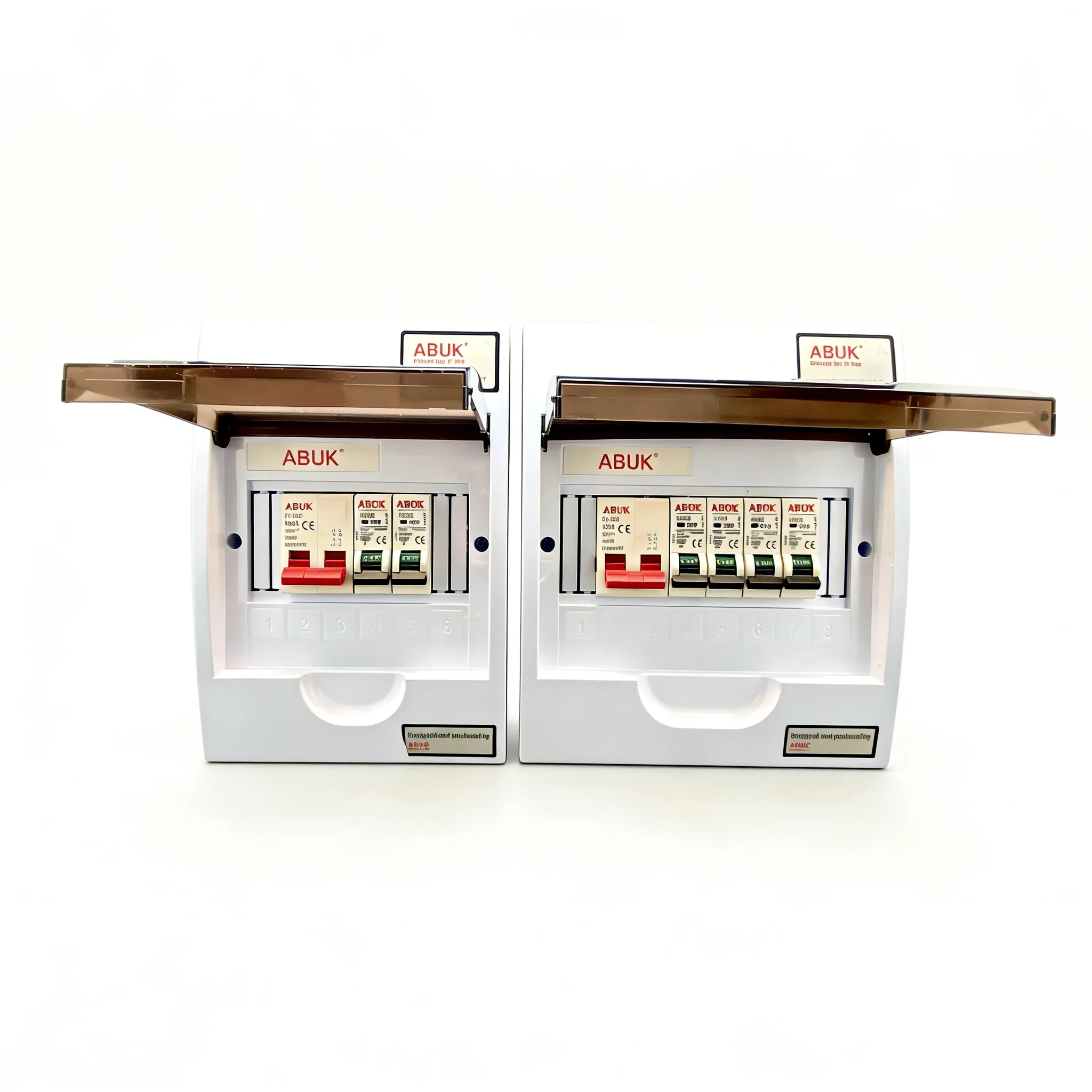
ABUK builds mechanical wall switches, wall switch socket solutions, distribution boards, and related electrical products for exactly that moment — when safe wiring, practical installation, and export-ready compliance must work together.
Explore ABUK wall switch socket solutions here.