
 Wenzhou Lita Electric Co., Ltd.

How to Connect a Double Switch Socket?
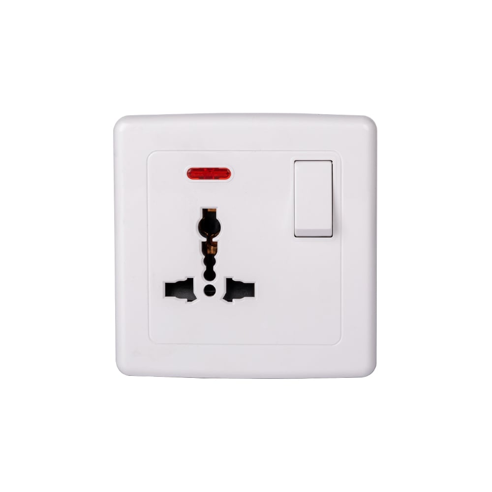
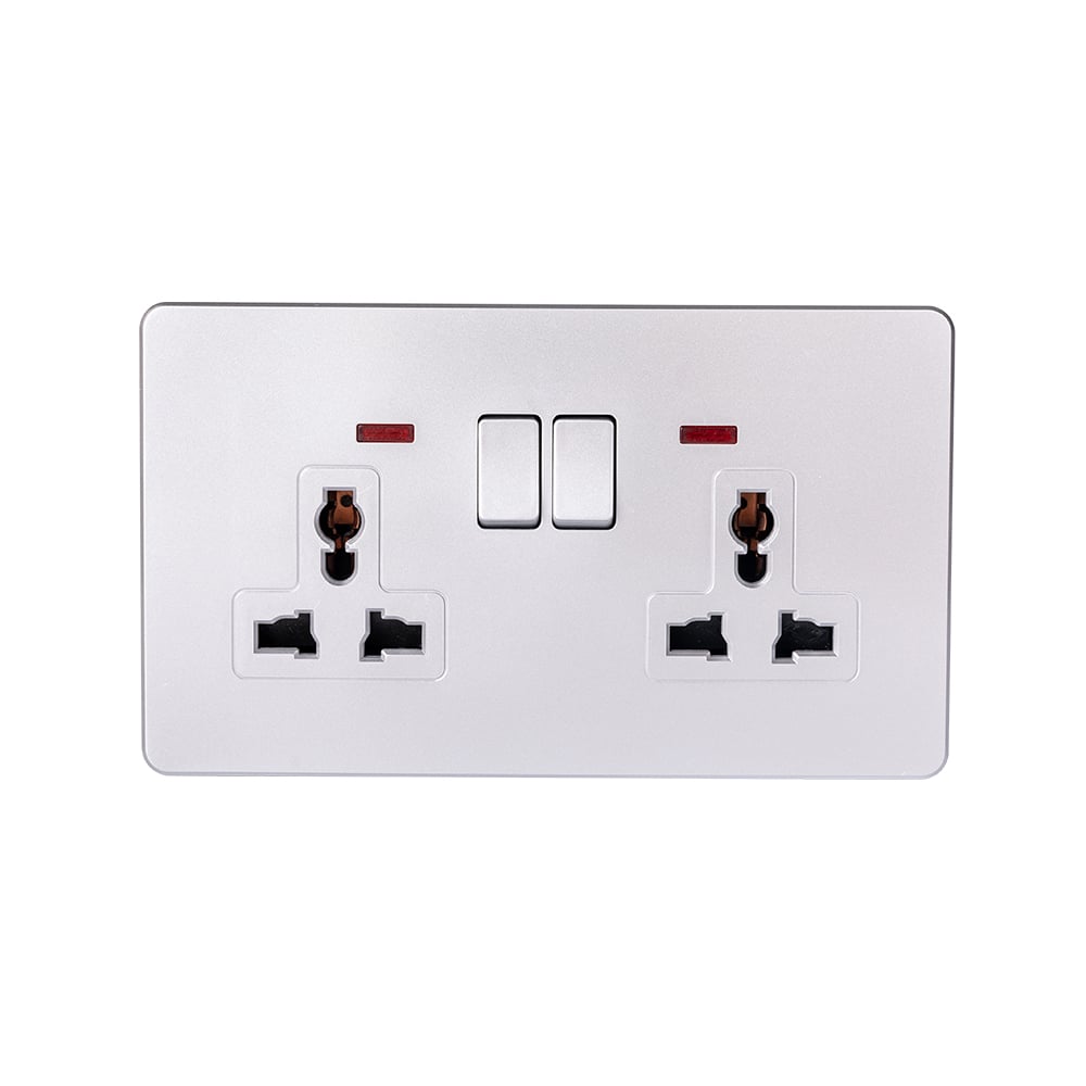
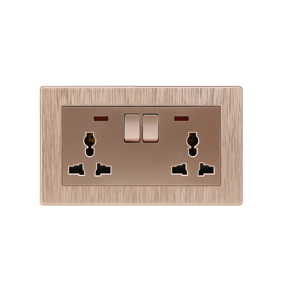
A double switch socket can describe two switch controls beside a socket, a double-gang accessory, or a socket controlled by a double-pole switch. Those are not interchangeable wiring arrangements. Ordering by the front photograph alone can leave an installer with the wrong switching function, insufficient back-box space, or a circuit arrangement that the accessory does not support. A double switch with socket must therefore be identified by its exact model, terminal diagram and intended loads before connections are planned. This guide explains the distinctions, the conditions for shared feeds, and the checks a qualified electrician needs before installing and testing the finished unit.
The short answer is that a qualified electrician connects the unit according to the manufacturer’s diagram and the verified circuit design, not a universal terminal recipe. Two gangs describe a physical layout; two poles describe two electrically separate contact paths operated together. A double pole switch socket may disconnect line and neutral in a single-phase application, but that must be confirmed for the specific model. Separate lighting controls need separate switched outputs. Before work, the electrician must identify every supply, isolate and verify absence of voltage, and confirm protective-earth continuity. Socket compatibility, ratings, circuit protection and box capacity also need checking.
Before selecting a double accessory, compare its terminals and isolation steps with the switch outlet combo wiring guide.
Does double mean two controls or two switched poles?
A gang describes a position or control on an accessory; it does not establish the number of electrical poles. The phrase double light switch socket is particularly ambiguous because it may mean two independently operated lighting switches combined with a socket, rather than a double-pole mechanism. A double-gang plate can also carry two sockets and no separate lighting control. Procurement descriptions should state the actual function, not rely on the word double.
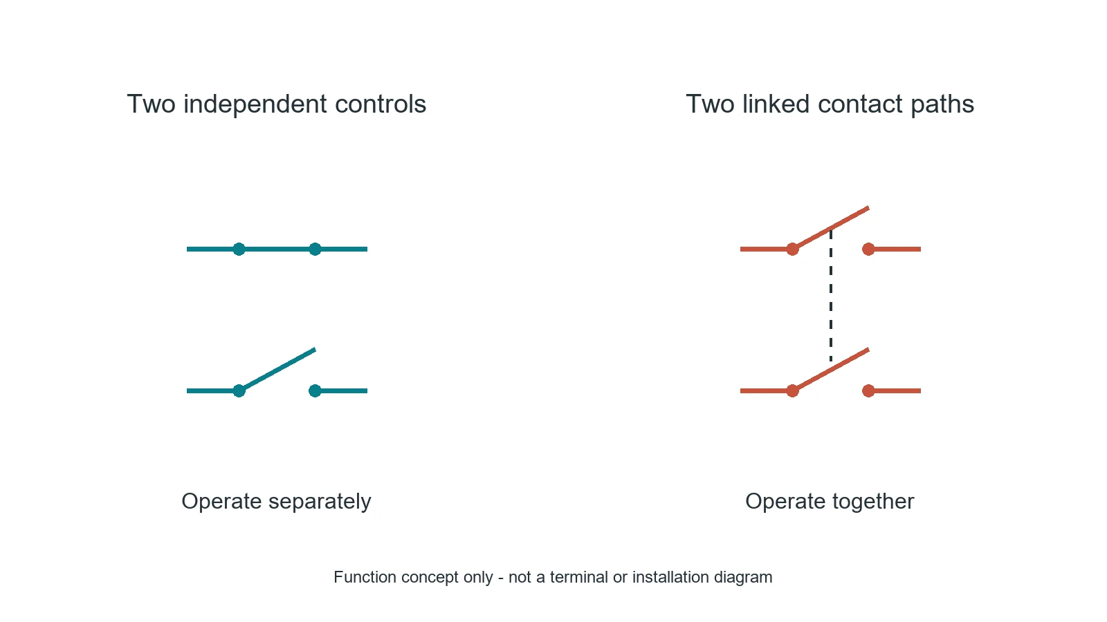
A double-pole mechanism operates two contact paths together. In an appropriate line-and-neutral application, opening the mechanism disconnects both of those conductors. That does not provide independent control of two lights, and it does not disconnect protective earth. Whether the accessory is suitable as an isolating device requires its own documentation and the applicable installation rules; a DP label alone does not answer that question.
| Description | What it establishes | What still needs verification |
|---|---|---|
| Two independent switches beside a socket | Separate controls can operate separate loads if the design supports them | Individual switch functions, separate outputs, socket supply and permissible common feed |
| Double-gang accessory | The accessory occupies a two-gang format | Whether it contains switches, sockets or a combination; compatible box and plate |
| Double-pole switched socket | Two contact paths are operated together as documented | Which conductors are switched, socket rating and any isolation suitability |
| Separate DP switch and separate socket | The devices are distinct components | Whether the installation design permits the intended supply relationship and mounting arrangement |
What must an electrician establish before connecting the unit?
The first task is circuit identification. A combined light switch and outlet can contain more than one supply, and switching one breaker off does not prove that every conductor in the box is dead. The electrician must establish the supply origin, protection, existing conductor functions and any shared-neutral or multi-circuit arrangement before disconnection. Wire colour, a previous connection or the accessory’s front appearance is not sufficient evidence of conductor function.
Isolation must cover every relevant source, including any identified alternative supply. It must be secured against inadvertent reconnection, followed by an appropriate absence-of-voltage check. In UK workplaces, HSE’s Electrical safety: FAQs describes competence in terms of the training, knowledge and experience needed for the work. In US workplaces, OSHA 29 CFR 1910.333(b) addresses de-energizing, lockout/tagout and verification; paragraph (b)(2)(iv) requires a qualified person to test exposed circuit elements and consider induced voltage or backfeed. These are jurisdiction-specific safety references, not interchangeable installation codes.
The manufacturer’s terminal diagram then establishes whether the mechanism has separate common terminals, factory links, removable tabs, neutral terminals or a socket controlled internally by a switch. Markings such as L, N, COM or numbered outputs must be interpreted from the documentation for that exact model. If the rear markings and supplied diagram disagree, installation should stop until the manufacturer resolves the discrepancy.
When are bridges or pigtails acceptable for separate loads?
For a double switch with socket, a shared supply is possible only when the verified circuit design, accessory instructions and local rules permit it. A factory link may distribute a common feed; alternatively, an approved connector and suitably rated pigtails may be used when specified or permitted. Neither arrangement is a default. The electrician must confirm conductor size and type, terminal capacity, connector suitability, protective-device coordination and the combined load conditions.
Independent circuits must never be bridged together. That includes joining their line conductors or casually sharing their neutrals because the devices sit under one faceplate. A manufacturer’s removable link must only be configured as its instructions allow. Where separate supplies occupy the same enclosure, their acceptability, identification and isolation arrangements require an explicit installation design.
Two independently controlled lights require two distinct switched outputs and the appropriate switch functions. A double-pole control is not a substitute: its contacts move together. A socket may remain continuously supplied, or may be switched, only if the model and circuit arrangement support that behavior. The load description must therefore specify whether each control operates a light, the socket, or another permitted load before the accessory is selected.
How are line, neutral and earth treated without guessing terminals?
Line provides the supply path and, where applicable, the outgoing switched feed. Neutral provides the return path for loads that require it; it is not assumed to be present at an older switch location. A double pole switch socket can have documented supply-side and load-side connections for line and neutral, but their positions must come from the exact wiring diagram. Some switch-only mechanisms do not need a neutral connection at the switch itself.
Protective earth is a separate safety function. Its continuity must be maintained, and required earth terminals on the accessory and metal box must be connected as the design and local rules require. Protective earth must not be routed through a switching pole, used as a neutral or treated as a spare conductor. An accessory that appears to function correctly can still have a defective protective-earth connection.
This article intentionally provides no universal terminal-to-wire diagram. Such a diagram would require a confirmed product terminal layout, supply system and circuit topology. The useful deliverable for an installer is the model-specific diagram together with verified circuit information and a defined inspection and test scope.
Why do box depth and faceplate compatibility affect cost?
A plate that fits the wall opening does not prove the assembly fits safely behind it. Combined wall switches and sockets need room for mechanism depth, conductor bends, connectors and the required terminations. The minimum box depth is model-specific; there is no reliable universal dimension for every double unit. Cables must not be pinched, terminals stressed or the accessory forced into place.
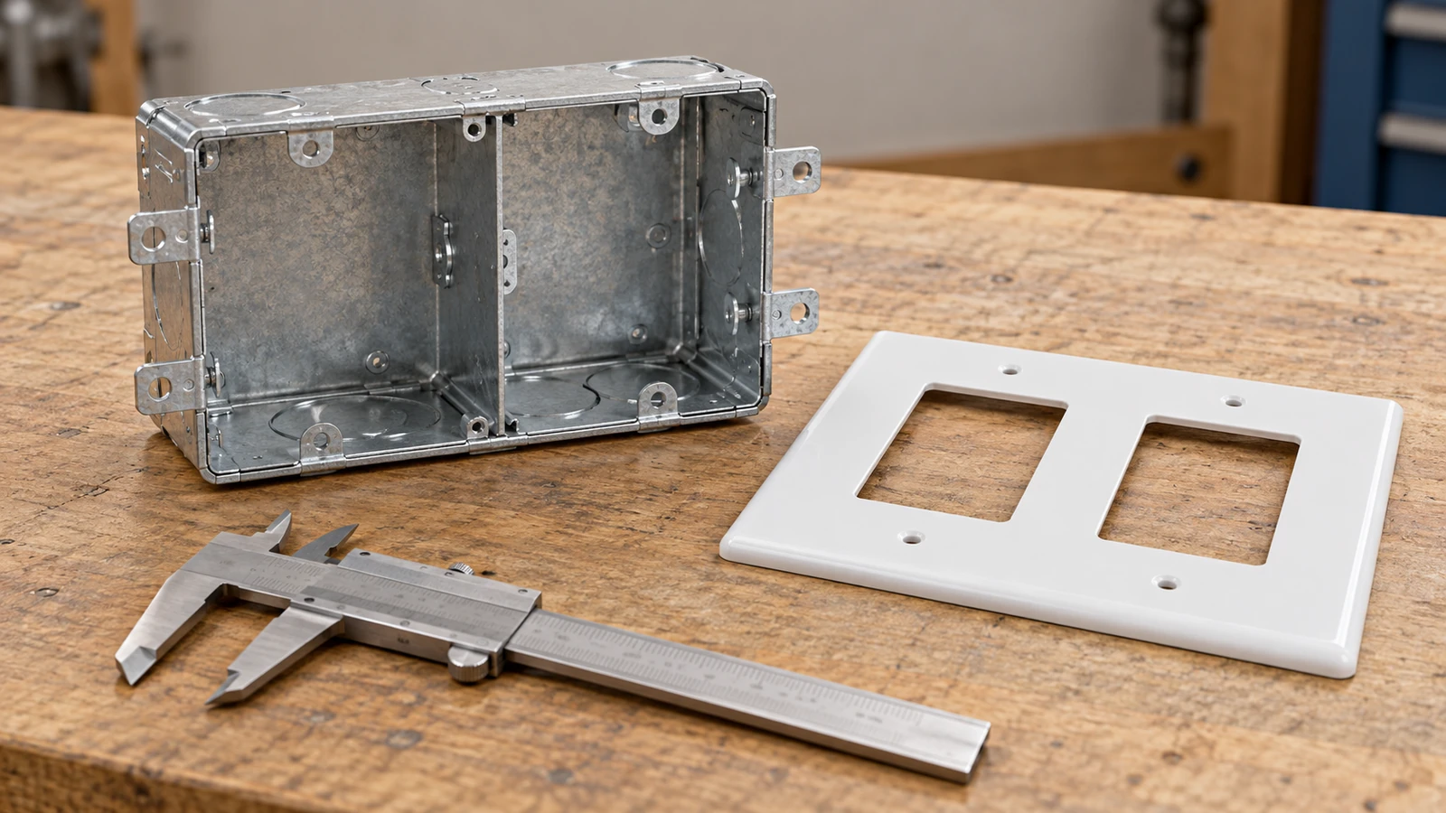
The following comparison uses installation scope rather than unverified prices. It identifies where a cheaper accessory can create extra work, without assigning a monetary saving or claiming measured reliability differences.
| Check | Evidence needed before purchase | Potential cost if omitted |
|---|---|---|
| Mechanism and box depth | Manufacturer’s depth requirement plus measured available space | Box replacement, wall work or accessory reselection |
| Faceplate and mounting compatibility | Matching series, mounting centres and supported module combination | Replacement plates or a mismatched assembly |
| Terminal and connector capacity | Permitted conductor count, size, type and specified tightening method | Re-termination or revised connection layout |
| Switching and supply arrangement | Exact terminal diagram and circuit schedule | Wrong-function purchases, delayed commissioning or circuit redesign |
| Destination-market documentation | Applicable product documentation and installation requirements | Approval delays or refusal to accept the installation |
Which safety and compliance checks remain necessary?
Product conformity and installation verification answer different questions. The European Commission’s CE marking guidance explains that the marking indicates the manufacturer’s declaration of conformity with applicable EU requirements. It is not a circuit diagram, a guarantee of compatibility with a particular box, or an installation approval. The Commission’s RoHS Directive guidance concerns restrictions on hazardous substances in electrical and electronic equipment; it does not establish a socket’s load rating or correct conductor arrangement.
Applicability depends on the destination market and the specific product. Procurement teams should obtain the relevant declaration and supporting model identification rather than infer conformity from a family photograph or a supplier’s general claim. Local installation rules determine matters such as circuit protection, permitted wiring arrangements and required inspection, testing and certification.
Before energizing, the electrician should complete the inspections and tests required for the installation, including protective-conductor continuity and polarity where applicable. After safe restoration, functional checks must confirm that each intended load has the correct control and that the socket has the specified switched or continuously supplied behavior. A successful on/off test does not replace electrical safety verification.
What should buyers request for the correct combination?
Specify the function first: independent lighting controls, a switched socket, or double-pole operation. Next, request the exact model diagram, electrical and load-type ratings, terminal limits, box-depth requirement and compatible faceplate. Finally, confirm how the chosen arrangement will be inspected and tested in the destination market. These checks are more useful than searching for a visually similar double pole combination switch socket.
For ABUK wall switches and sockets, the S10 series page is a starting point for model selection, not evidence that every combination is available or interchangeable. The sockets and switches in the S08 series should likewise be checked against their own mounting and accessory documentation. Series appearance alone cannot establish cross-series fit.
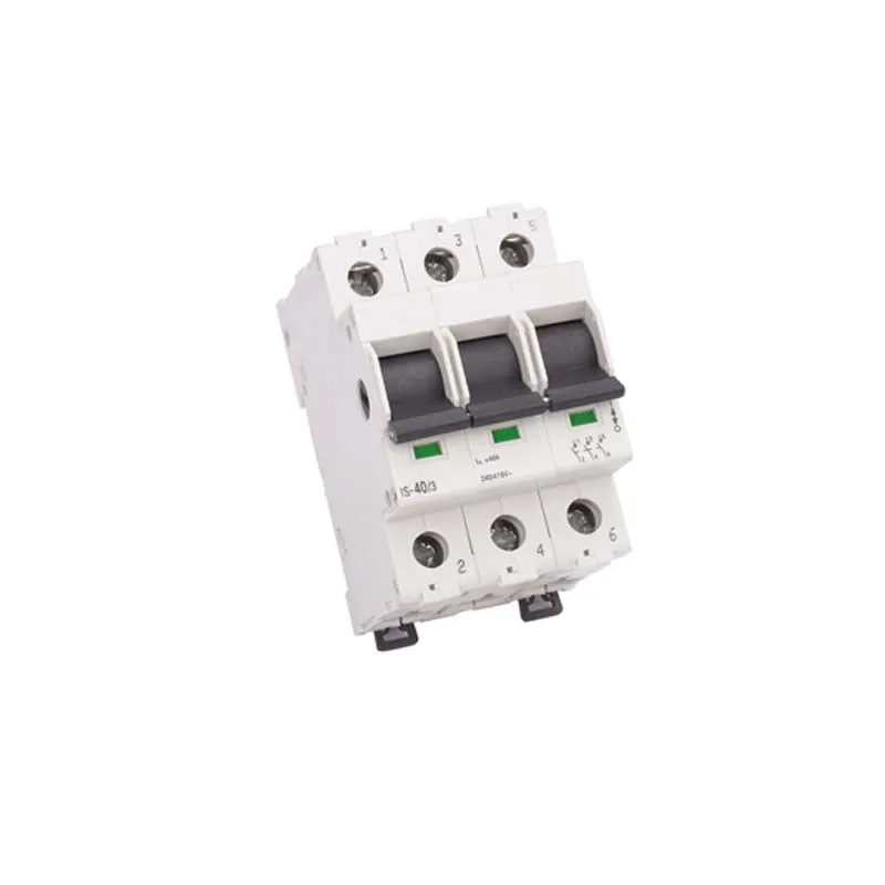
The listed 20A S10 DP switch is specifically a separate switch, not a combined socket product. Its page can help identify a DP-switch component, but suitability for controlling a particular socket circuit still requires the product documentation and installation design. No terminal assignment or combination compatibility is established here.
What else should installers and purchasers know?
How do you connect a double switch socket?
A qualified electrician identifies the precise accessory and all supplies, isolates and verifies absence of voltage, then follows its documented terminal layout and the approved circuit design. A double switch with socket has no universal connection pattern, so the required switched outputs and socket behavior must be confirmed before wiring. Installation finishes with the required inspection, electrical tests and functional checks.
What is a double-pole combination switch socket?
It is a combined accessory in which a double-pole mechanism operates two documented contact paths together, commonly line and neutral where that arrangement is specified. A double pole switch socket is not the same as two independently operated switches. Its exact internal connections and any isolation suitability must be verified from the model documentation.
Can two lights share a double switch socket?
Two lights can have independent control if the accessory provides two suitable independent switch mechanisms and the circuit design supports their separate outputs. A common supply is permissible only under the documented and locally permitted conditions; separate circuits must not be bridged. A linked double-pole mechanism alone does not provide two independent controls.
How are line, neutral and earth connected in a double unit?
Line and neutral connect only to the supply and load terminals identified for the exact model and circuit arrangement. Protective earth remains continuous and connects to required accessory and enclosure earth points; it is not switched or substituted for neutral. Existing wire colours and the front face of the unit cannot establish those connections.
Which official references support these checks?
- HSE, Electrical safety: FAQs: competence and workplace electrical-safety guidance.
- OSHA, 29 CFR 1910.333, Selection and use of work practices: de-energizing, lockout/tagout and verification requirements in US workplaces.
- European Commission, CE marking: the marking’s meaning and manufacturer responsibilities.
- European Commission, RoHS Directive: restrictions on hazardous substances in electrical and electronic equipment.
Official references and the named product-page distinctions were reviewed on 8 October 2026. The comparison concerns function and installation scope, not tested product performance or market prices. ABUK is the product supplier discussed; no independent certification assessment of the named accessories is presented.
What is the final decision before installation?
The decisive distinction is between two controls and two poles: one concerns independent operation, while the other concerns linked contact paths. Start by defining the loads and identifying their supplies, then select the documented mechanism, verify its terminals and confirm that the box and faceplate support the assembly. Never bridge independent circuits to simplify the layout, and never accept working lights as proof of protective-earth continuity. Choosing wall switches and sockets is therefore a specification task before it becomes an installation task. ABUK’s product catalogue provides a route to candidate accessories; contact ABUK for the exact model diagram, dimensions and applicable documentation before the qualified installer finalizes the design.