
 Wenzhou Lita Electric Co., Ltd.

How to Wire a Combination Switch and Outlet
When a facilities coordinator in Denver encountered a request for an outlet beside a storeroom light switch, she bought a combination device after watching an installation video. In this hypothetical case, work stopped as soon as the electrician opened the box: the old switch loop had no neutral. The compact accessory fitted the opening, but the circuit could not support the proposed arrangement.
Summary: A combination switch and outlet needs a wiring arrangement supported by its exact instructions, including a neutral for the receptacle. Leviton’s 5225 example has a 15A, 125V receptacle and separate instructions for common and separate feeds. Terminal colors alone are insufficient. Identify the available conductors and intended switching function before choosing the device or changing any feed tab.
This guide addresses a common North American combination device: a switch and receptacle built on one mounting strap. It does not treat every switched socket sold worldwide as the same product. The distinction matters when comparing wiring diagrams or buying an accessory for a different country.
What should the switch control?
The first design decision is the intended result. An always-powered receptacle with a switch controlling a separate light is different from a receptacle whose power is controlled by the adjacent switch. A combination switch and outlet may support particular arrangements, but no arrangement should be assumed from its front appearance.
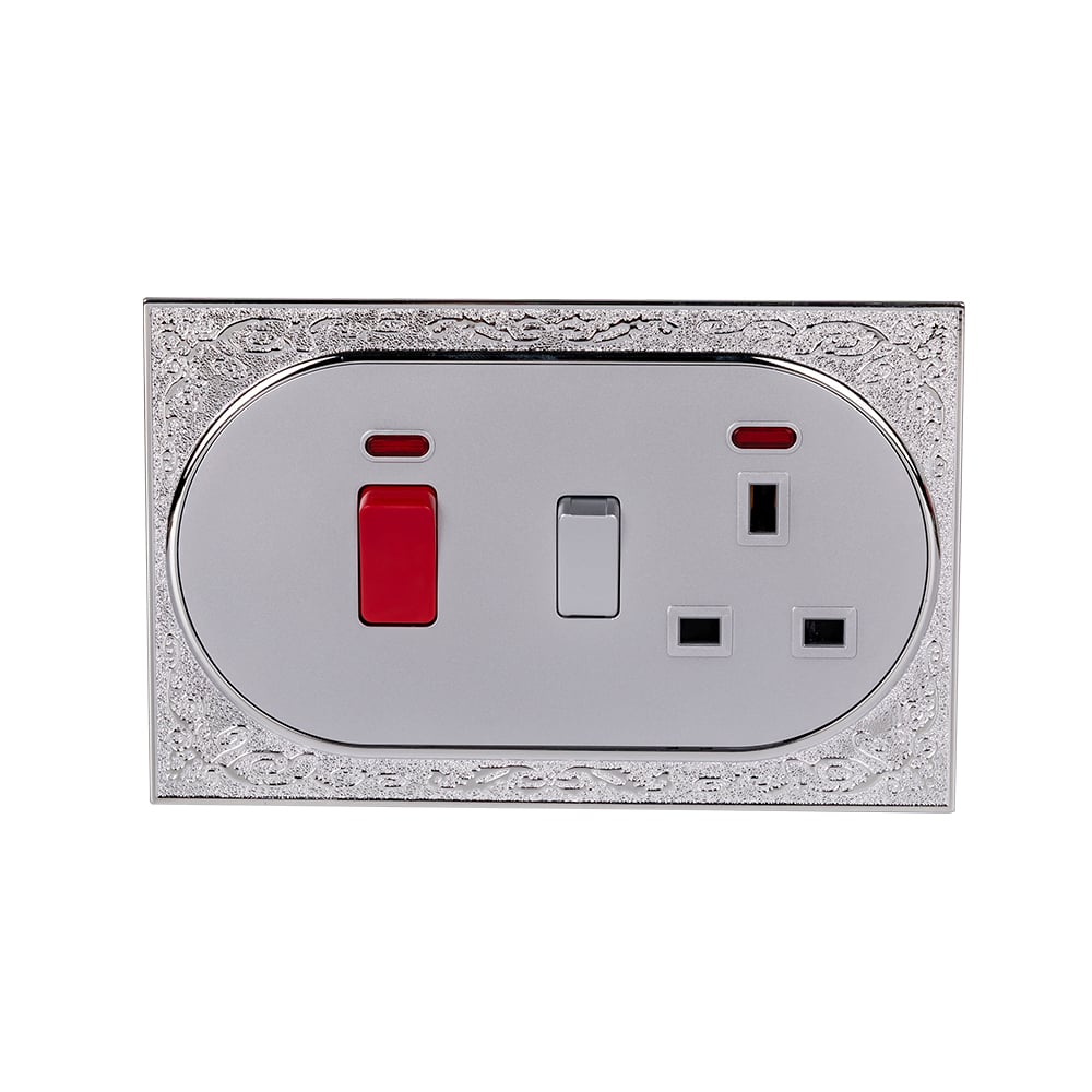
Leviton’s 5225 is one documented example: its receptacle is rated 15A, 125V AC and its single-pole switch is rated 15A, 120V AC. Its installation sheet shows the supported circuit arrangements. These are reference-model facts, not ratings for every combination accessory or for the products pictured here.
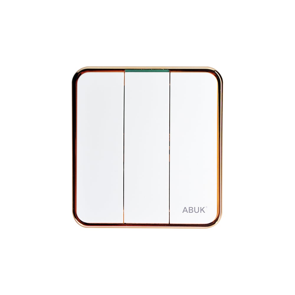
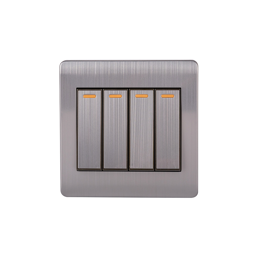
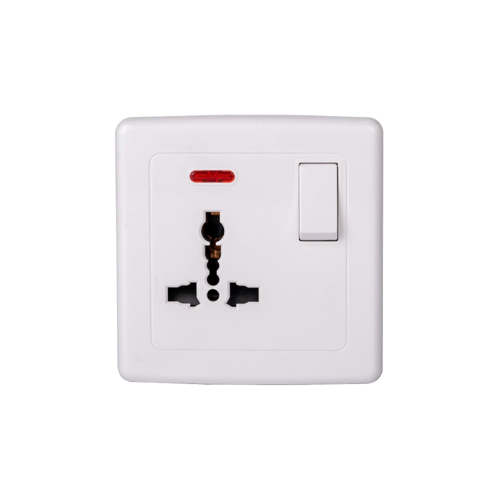
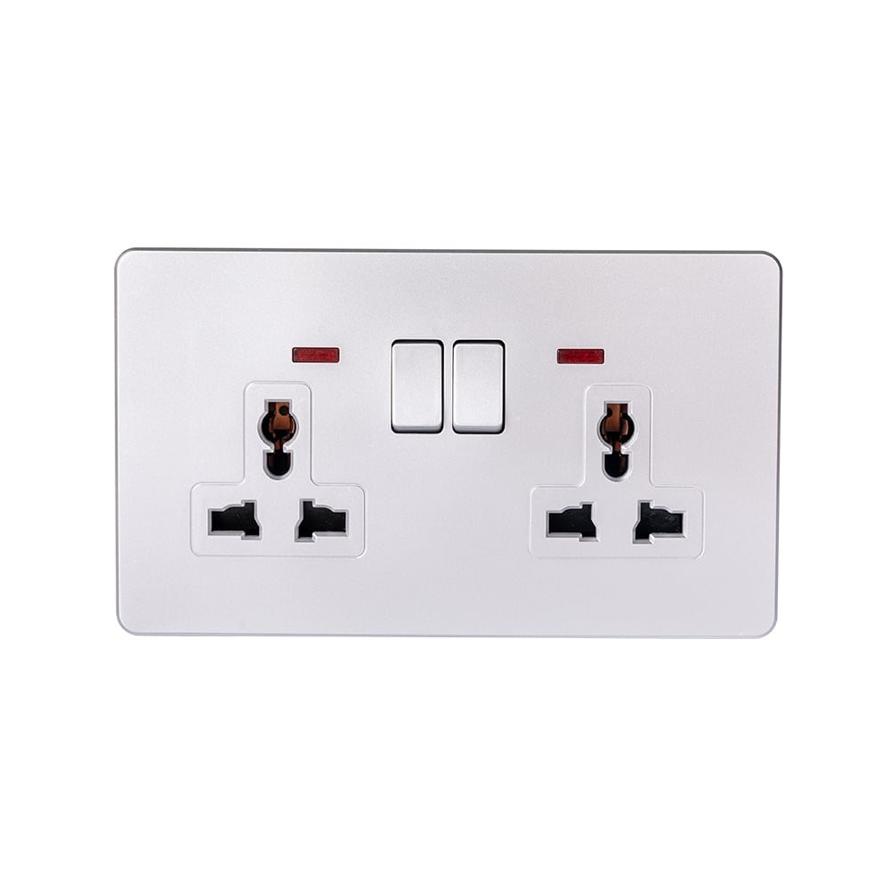
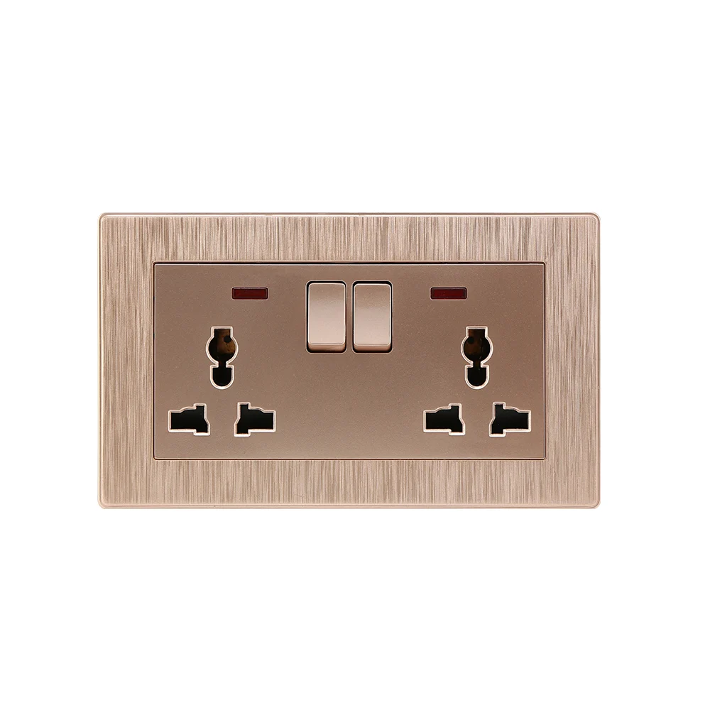
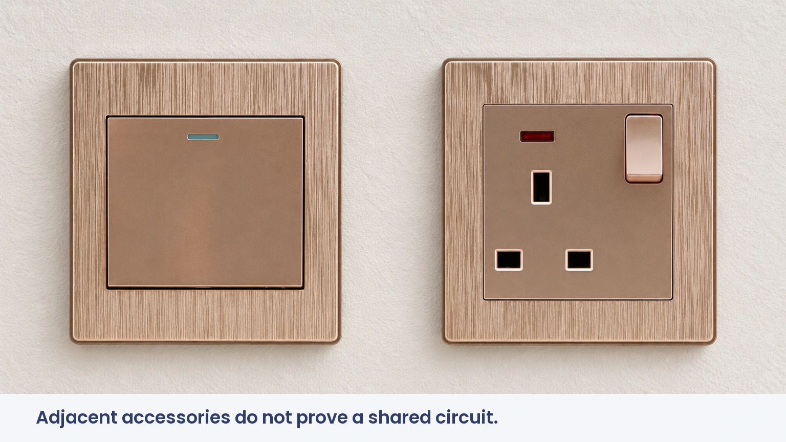
Two separate accessories mounted beside each other are not an integrated combination device. They may belong to different circuits or have no electrical relationship. The illustrated rocker and socket are separate product samples; their position does not establish an approved wiring diagram.
Why does neutral availability decide whether the job can proceed?
A mechanical light switch can interrupt the live conductor without using a neutral at the switch itself. A receptacle needs the circuit’s neutral as well as the required protective grounding arrangement. Consequently, an older switch box can contain enough wires to operate a light while lacking the conductors needed for an outlet.
The 5225 manufacturer’s sheet explicitly says that a neutral is required and warns against replacement of a switch with only two wires attached when that arrangement lacks the needed neutral. Wire count and insulation color still cannot establish function reliably: a reidentified conductor or a cable passing through the box may have another purpose.
The electrician must trace and verify the circuit. Using the equipment ground as a neutral is not a workaround; it would place normal operating current on the protective path. A neutral from an unrelated circuit is also not an acceptable shortcut. If the required conductor is absent, the cable route or the chosen outlet location needs to change.
When is the feed tab retained, and when can it be removed?
The common-feed tab links specified terminals on some combination devices. In a supported common-feed arrangement, that link allows one incoming supply to serve the relevant portions of the accessory. Removing it changes the internal connection and may leave part of the device unpowered unless the approved separate feed is provided.
For the 5225, the instructions identify the break-off fin and specify removal for the separate-feed, two-circuit arrangement. That does not authorize copying the same action onto a different model. A tab should never be removed merely because a photograph online shows it missing.
Two-circuit arrangements introduce a second isolation issue: switching off one breaker may leave another part of the box energized. The electrician must establish the permissible circuit arrangement, any shared-neutral implications, disconnect requirements and labeling under the locally adopted code. This is a design check, not just an extra wire connection.
How should the connection be made and verified?
Once the circuit design is settled, the work proceeds with isolation, prevention of reconnection and proof that all relevant conductors are dead. HSE GS38 offers useful principles for safe test equipment and verification, though it does not replace a US jurisdiction’s installation rules. A non-contact detector alone is insufficient to prove dead.
- Identify the exact device and use its current manufacturer diagram.
- Confirm conductor functions, feed arrangement, grounding and enclosure capacity.
- Terminate only the permitted conductor material and size using the specified preparation and torque.
- Mount without crushing insulation or forcing the accessory against crowded conductors.
- Verify the receptacle, switch operation, polarity and required protective measures before handover.
For the reference 5225, the sheet specifies a 5/8-inch strip length and 14–18 in-lb terminal torque. These values demonstrate why a model-specific sheet matters; they must not be reused as universal installation settings.
Which arrangement fits the room’s actual needs?
| Intended arrangement | Main requirement | Common mistake |
|---|---|---|
| Always-on outlet, separate switched light | Supported diagram and identified light conductor | Assuming the outlet must turn off with the light |
| Switch-controlled outlet | Device and circuit designed for that function | Copying a separate-light diagram |
| Separate feeds | Manufacturer support and code-compliant circuit design | Leaving a feed link in an incompatible arrangement |
| Old switch loop without neutral | New compliant wiring route or different outlet position | Borrowing ground or an unrelated neutral |
The least expensive device is not always the least expensive installation. A combination fitting can save wall space, yet a new neutral route, deeper box or revised protection may dominate the labour cost. Those conditions should be surveyed before a bulk order is approved.
What makes an apparently small retrofit expensive?
| Site condition | Work it may add | Question for the quotation |
|---|---|---|
| No suitable neutral | Cable replacement or rerouting | Is the new route included? |
| Limited box space | Box replacement and wall repair | Is making good included? |
| Wet or otherwise regulated location | Required protective-device arrangements | How will local protection rules be met? |
| More than one supply | Design review, isolation and labeling | How will future maintenance identify both feeds? |
Which approvals apply to the accessory and the installation?
The reference manufacturer’s listing, ratings and installation sheet should be checked alongside the locally adopted electrical code. Product approval does not authorize every possible circuit arrangement. NEMA 5-15R describes the receptacle configuration; it does not settle box fill, grounding or location-specific protection.
CE, RoHS and GCC-market documentation have different scopes and are not substitutes for North American product acceptance. Procurement should request the exact model’s destination-market evidence rather than accept a company-level certificate as proof for an unfamiliar combination device.
How can buyers avoid ordering the wrong combination?
- Describe what stays powered when the switch is off.
- Confirm the available conductors before choosing a model.
- Request the exact wiring sheet and mounting dimensions.
- Include testing, labeling and wall repair in the installation scope.
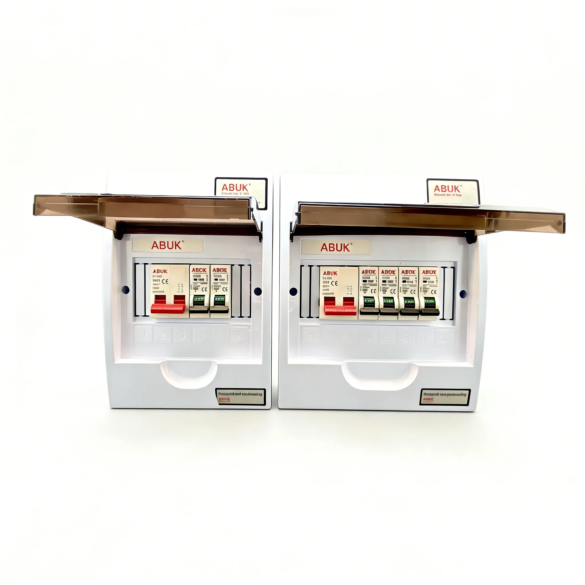
ABUK’s wall switches and sockets can be reviewed for projects needing separate accessories; a pictured switch and socket must not be assumed to form an approved integrated combo. The related switch-outlet combo guide provides broader context, while this article focuses on the circuit conditions that determine feasibility.
Frequently asked questions
How do you wire a combination switch and outlet?
A qualified electrician identifies the desired function and conductors, isolates all supplies, follows the exact device diagram and verifies the installation. There is no universal diagram for every combination accessory.
Does a combination switch outlet require a neutral conductor?
The receptacle requires a suitable neutral. An old two-wire switch loop may not provide one, even though it operated the original mechanical switch correctly.
Can the switch control a separate light?
Yes, when the device supports that arrangement and the required circuit conductors are present. The outlet can remain powered; a switchable outlet is a different intended function.
How do you wire a combo device with two circuits?
Only according to its separate-feed instructions and local code. Feed links, isolation, neutral arrangements and labeling need professional review; both supplies must be accounted for during maintenance.
References
- Leviton 5225: ratings and product documentation
- Leviton 5225 installation instructions
- HSE GS38: electrical test equipment
A compact fitting saves space only after the circuit has been understood. For project sourcing, ask ABUK about accessory requirements with the destination market and the intended switching function clearly stated.