
 Wenzhou Lita Electric Co., Ltd.


How to Test a Wall Socket With a Multimeter
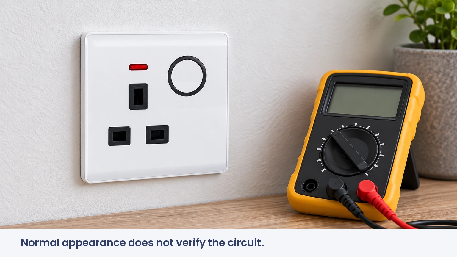
When a maintenance manager in Bristol encountered a workstation that kept losing power, he saw a normal voltage reading and assumed the socket was healthy. In this hypothetical example, the appliance failed again under use. The reading was real, but the conclusion was too broad: measuring voltage had not verified the complete circuit or its performance under load.
Summary: A multimeter can measure AC voltage at a wall socket; it cannot by itself certify polarity, protective earthing or circuit safety. Typical nominal supplies are 230V in the UK and 120V for common US receptacles. Fluke specifies AC-voltage mode and the COM and voltage inputs. Live socket testing requires competence, suitable equipment and a controlled method; untrained users should arrange an electrician.
Searching for a single “good” number misses the most useful part of diagnosis: what the instrument measured, between which points, under what conditions, and which faults remain possible afterward.
Which multimeter setting and inputs are used for socket voltage?
For AC supply voltage, the instrument must be in its AC-voltage function, commonly marked V~. Fluke’s measurement guidance places the black lead in COM and the red lead in the voltage input, often marked V or VΩ. The instrument’s own instructions govern the exact arrangement.
The A or mA input is not an alternative voltage input. A meter connected across a supply while configured for current measurement can create a dangerous short circuit. Resistance and continuity functions also do not belong on an energized socket. An electrician checks the function, lead positions and range before approaching the test points.
If a manual-ranging meter is used and the voltage is uncertain, Fluke advises starting with a suitable higher range. That does not make an underrated instrument safe: its voltage rating, measurement category, leads and probes must all suit the installation.
Why do the meter category and probe condition matter?
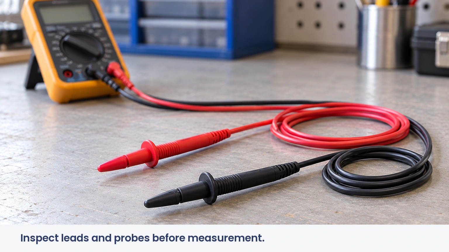
HSE GS38 identifies CAT III with building wiring, including socket-outlets, while CAT II relates to appliance-level circuits. A category label describes the transient environment for which equipment is designed; it is not interchangeable with the largest number on the display. The entire measuring assembly must be suitable, including accessories.
GS38 recommends probe tips exposed by no more than 4mm, preferably 2mm, with suitable finger barriers and insulation. It also references relevant probe and voltage-indicator standards, including BS EN 61010-031 and BS EN 61243-3. Damaged insulation, loose plugs or exposed metal beyond the intended tip are reasons to stop.
Proving an installation dead is a separate safety task. A non-contact pen alone is insufficient; a suitable voltage indicator must be checked before and after use according to the safe-isolation procedure. Live measurement should only be undertaken where justified and by someone competent to control the risks.
What should a voltage reading show—and what can it miss?
A typical UK wall socket is supplied at nominally 230V AC, while a common North American receptacle is supplied at nominally 120V. Actual readings vary with the local supply specification, load and wiring conditions. There is no universal pass band that applies to every country, circuit and instrument.
An electrician may compare live-to-neutral, live-to-earth and neutral-to-earth readings where the system and safe test method allow. Each comparison answers a different question. A small neutral-to-earth potential can reflect voltage drop under load; a particular value alone does not establish a fault or prove correct bonding.
AC voltage also does not behave like a DC battery polarity test. Swapping probes does not produce a reliable positive/negative indication of which socket contact is live. A normal live-neutral reading can exist with reversed conductors, an inadequate protective earth or a high-resistance connection that deteriorates when current flows.
Why can a digital meter show voltage on a disconnected conductor?
Fluke describes how a high-input-impedance meter can detect capacitively coupled “ghost” voltage. Its dual-impedance guidance explains that high-impedance inputs, often above 1MΩ, draw very little current; nearby energized wiring can therefore influence a reading on an otherwise disconnected conductor.
A suitable low-impedance function can help a trained person distinguish some coupled readings, but it must be used within the instrument’s instructions and the circuit’s limitations. Loading a sensitive electronic circuit can create other problems. A surprising reading must never be dismissed as harmless solely because ghost voltage is possible.
This is a common gap in simple testing guides: the meter affects the measurement. A credible diagnosis records the instrument and function used, rather than comparing every number with a generic online chart.
How should common results guide the next investigation?
| Observation | Possible explanation | What it does not establish |
|---|---|---|
| Expected nominal voltage | Supply potential present at the test points | Sound terminals, protective earth or load capacity |
| No voltage indicated | Isolated supply, open conductor or test problem | Safe isolation without a proper proving procedure |
| Unstable or unusual voltage | Supply variation, poor connection or instrument issue | A specific failed component |
| Voltage on an apparently disconnected point | Backfeed, coupling or incorrect circuit identification | Permission to touch the conductor |
Which test answers the maintenance question?
| Question | Useful approach | Limit |
|---|---|---|
| Is supply voltage present? | Controlled voltage measurement | Only the tested condition and points |
| Are selected connections wrong? | Suitable polarity testing | Basic plug-in indicators miss some faults |
| Will protection operate correctly? | Applicable installation tests | Not answered by voltage alone |
| Why does the appliance fail during use? | Appliance and circuit investigation | A no-load reading can overlook the cause |
For a facilities team, this distinction saves unnecessary replacements. Recording the appliance, time, affected outlets and observed symptoms gives the electrician more useful evidence than repeatedly taking an isolated voltage reading.
Which standards apply to electrical socket testing?
IEC/EN 61010 equipment requirements and HSE GS38 guide instrument selection and safe working. Installation verification must follow the applicable national rules, such as BS 7671 in the UK. A meter’s conformity marking does not make every measurement method appropriate.
CE, RoHS or GCC documentation for an accessory does not show that the installed circuit passed testing. Product documentation, test-equipment suitability and installation results are separate records. Mixing them can leave a property manager with plenty of paperwork but no evidence addressing the actual fault.
What should a property team prepare before calling an electrician?
- Record which electrical socket outlets are affected and whether the problem follows one appliance.
- Note trips, smells, sounds or visible damage without opening the accessory.
- Provide circuit labels and earlier inspection records where available.
- Ask for findings and the reason for any proposed accessory replacement.
ABUK’s replacement sockets and switches can be considered after the fault and required specification are established. For home electrical outlets, related issues such as socket sparking and water in a plug socket need their own diagnosis rather than a reassuring voltage number.
Frequently asked questions
How do you test a wall socket with a multimeter?
A competent person uses an appropriately rated meter in AC-voltage mode, with correct inputs and a controlled live-test procedure. Untrained users should not insert probes into mains sockets.
What voltage should a wall socket show on a multimeter?
The expected value depends on the local supply: commonly nominal 230V in the UK or 120V for standard US receptacles. The applicable tolerance and test conditions determine interpretation.
Which multimeter setting is used for an AC outlet?
AC voltage, usually V~, with leads in COM and the voltage input. Current, resistance and continuity settings must not be used across an energized supply.
How can I check polarity without touching live conductors?
A suitable plug-in tester can screen for certain errors without exposed-probe contact, but it cannot verify every fault. Comprehensive polarity and installation verification should be performed by an electrician.
References
- Fluke: measuring AC voltage
- Fluke: testing leads and probes
- Fluke: dual impedance and ghost voltage
- HSE GS38: electrical test equipment
- HSE: socket-tester limitations and safe working
A useful test result narrows the problem; it does not claim more than the instrument measured. Contact ABUK about replacement accessory specifications once the circuit requirements and repair scope are known.