
 Wenzhou Lita Electric Co., Ltd.
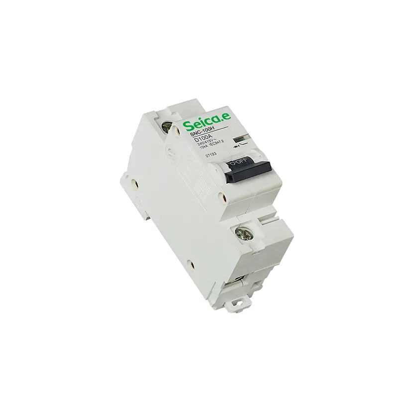
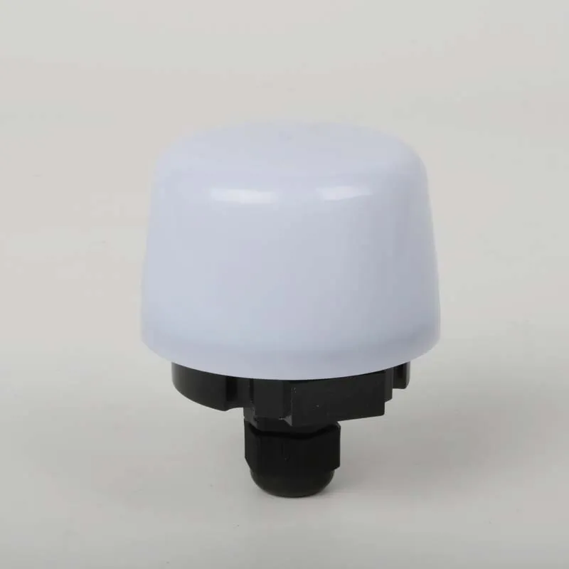
What Is a Lighting Control Module?
When a commissioning engineer in Dubai encountered unstable corridor lighting, he downloaded a wiring sketch, connected a new control unit with confidence, and expected the floor to pass testing that afternoon. Within minutes, several luminaires flickered and the DALI scan found no addresses, delaying handover by two days. The module was not defective—the team had connected an analog 0–10 V device to a digital control network. The question behind the failure was simple: what is a lighting control module, and which signals can it actually control?
Summary: A lighting control module receives commands from switches, sensors, timers, or a building-management system and converts them into relay, dimming, or digital lighting outputs. Selection must match supply voltage, load type, channel rating, inrush current, protocol, enclosure, and applicable standards. DALI-2 systems can address up to 64 control gear devices per bus segment; analog 0–10 V, dry-contact, and phase-control modules are not interchangeable.
A lighting control module is the interface between a control decision and an electrical lighting load. Some products simply open or close a relay; others dim drivers through 0–10 V, phase control, DALI, or another protocol. The DALI Alliance bases DALI-2 certification on the IEC 62386 family, while electronic switching products may also fall within IEC 60669-2-1. That standards split matters because a compatible connector does not prove compatible signaling.
What Does the Module Control?
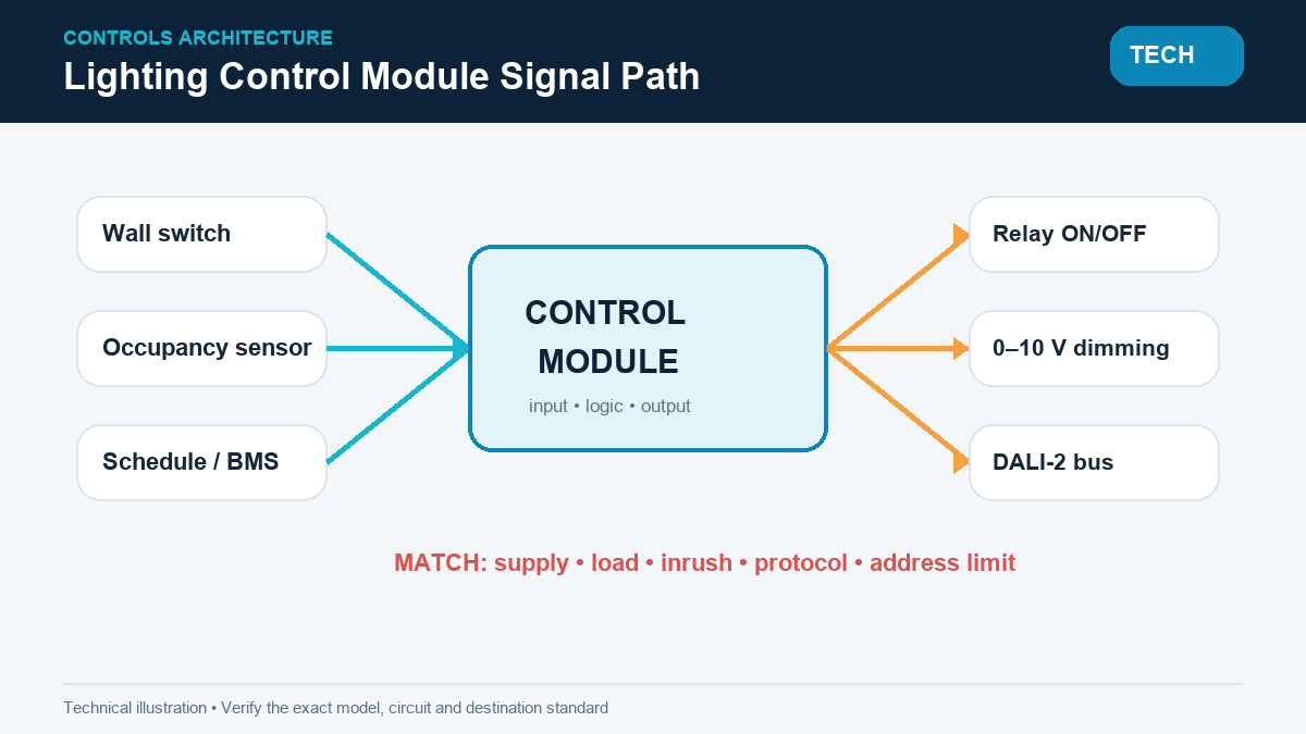
The module normally performs three jobs: it receives an input, applies logic, and changes an output. Inputs may include a wall switch, occupancy sensor, photocell, schedule, or building-management command. Outputs may be a 10 A or 16 A relay, a 0–10 V control pair, a phase-dimming channel, or an IEC 62386 DALI bus. A stated 16 A resistive rating should not be applied automatically to LED drivers; driver inrush can be many times steady-state current, so the manufacturer’s LED-load table and maximum driver count are more useful than the faceplate ampere value.
Which Control Types Are Common?
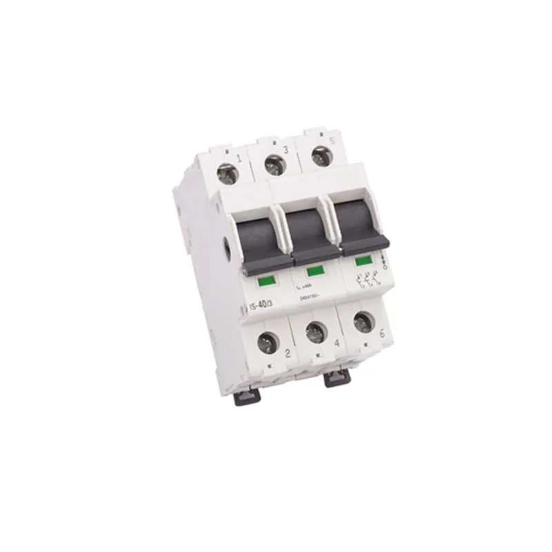
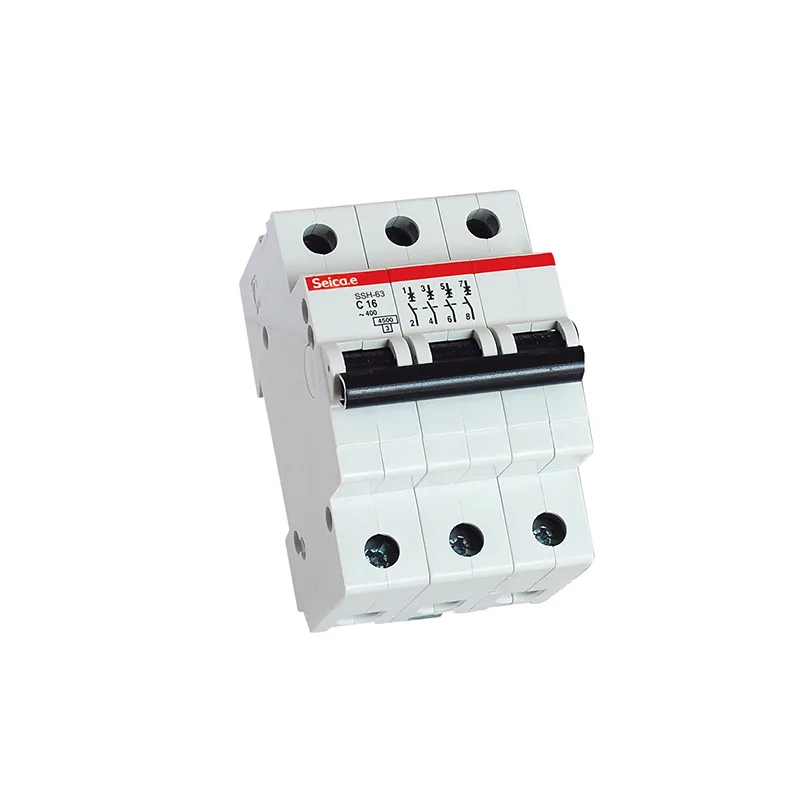
- Relay modules: provide on/off control and must be checked for pole arrangement, contact rating, and load category under IEC 60669-2-1 or the specified product standard.
- 0–10 V modules: use an analog control pair; polarity, source/sink behavior, isolation, and minimum dim level must match the driver.
- DALI-2 modules: communicate digitally; one DALI line typically supports up to 64 individually addressed control gear devices and 16 scenes under IEC 62386 architecture.
- Phase-control dimmers: use leading- or trailing-edge control; minimum load, driver compatibility, and thermal derating determine whether dimming remains stable.
How Is Compatibility Verified?
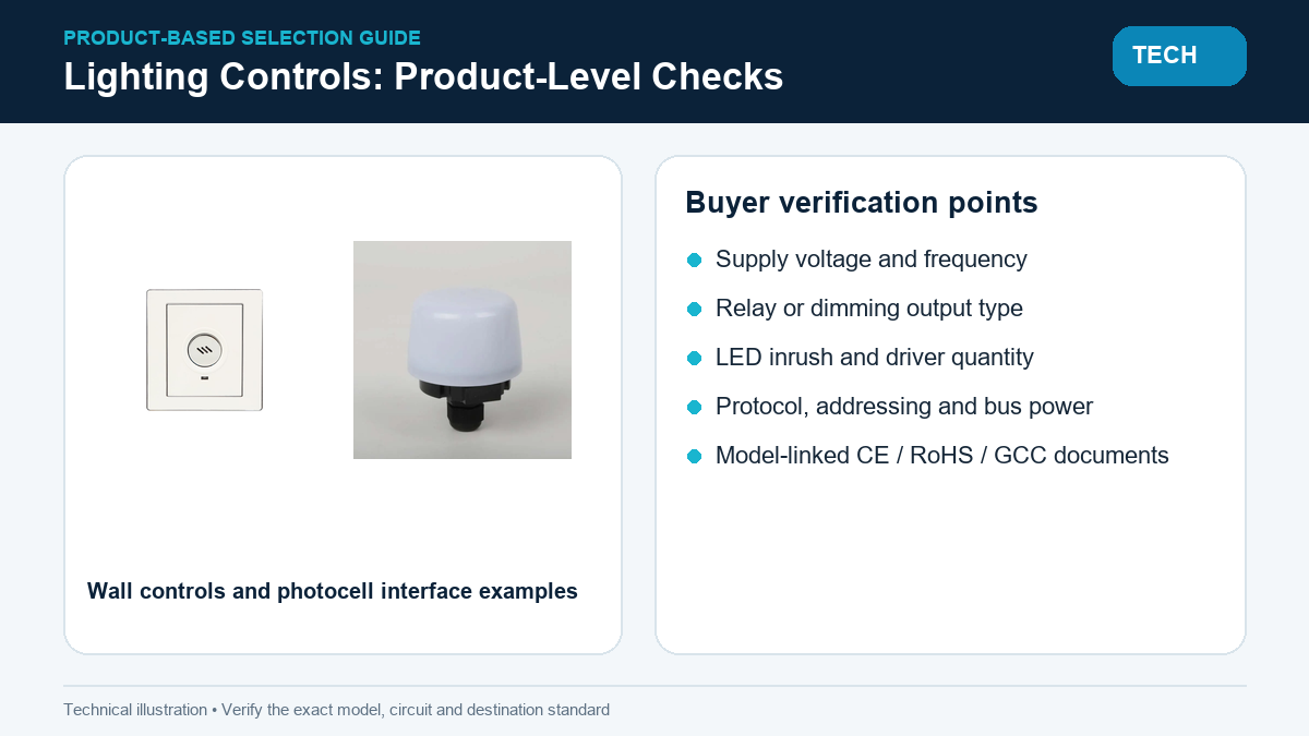
Compatibility requires more than a matching voltage. The engineer should verify the 50/60 Hz supply, channel current, LED inrush, protocol edition, bus power, cable length, addressing limit, enclosure temperature, and short-circuit behavior. For DALI wiring, the control pair is normally polarity-insensitive, but it is not a SELV assumption by default; insulation and routing must follow the equipment instructions and local installation rules. For 0–10 V wiring, polarity and separation rules may differ, so an IEC 62386 label cannot be inferred from two control terminals.
Where Do Hidden Costs Appear?
Specification errors become expensive during commissioning. If 200 rooms require 0.30 extra labor-hour for tracing and readdressing at USD 45 per hour, corrective labor reaches USD 2,700 before replacement hardware, access equipment, and delayed occupancy. ROI comes from confirming the signal and driver list during submittal review; choosing a cheaper incompatible module rarely survives the first commissioning day.
Control Module Comparison
| Dimension | Relay | 0–10 V | DALI-2 | Phase dimming |
|---|---|---|---|---|
| Primary function | On/off | Analog dimming | Addressed digital control | Mains waveform control |
| Typical capacity signal | 10–16 A resistive | Channel sink/source limit | Up to 64 control gear addresses | Wattage + driver count |
| Commissioning | Low | Low–medium | Medium–high | Medium |
| Compatibility risk | LED inrush | Polarity and driver range | Addressing and bus power | Flicker and minimum load |
| Best fit | Simple zones | Local dimming | Networked buildings | Retrofit dimming |
Application Matrix
| Application | Typical module | Critical check | Standards signal |
|---|---|---|---|
| Hotel room | Relay or scene module | Card switch, contact rating, manual override | IEC 60669-2-1 |
| Open office | DALI-2 controller | Addresses, groups, scenes, bus supply | IEC 62386 |
| Warehouse | Photocell + relay | LED inrush and sensor range | IEC 60669 series |
| Retrofit room | 0–10 V or phase dimmer | Existing cable and driver compatibility | Project-specific listing |
Standards and Compliance
- IEC 62386: digital addressable lighting interface requirements and device behavior.
- IEC 60669-2-1: particular requirements for electronic control devices and switches for fixed installations.
- CE: the applicable EU directives may include Low Voltage, EMC, and RoHS obligations; a CE mark is not a protocol certificate.
- RoHS and GCC/GSO: documents must match the exact model, factory, voltage, and destination market.
Noncompliance can cause EMC failure, unreliable dimming, rejected submittals, or wholesale reprogramming after occupancy. The honest answer is that certification scope and interoperability evidence must be reviewed separately.
Selection Guide
- Freeze the luminaire driver schedule before selecting control outputs.
- Calculate channel load from driver quantity and inrush, not only steady watts.
- Define protocol, addressing, scene count, manual override, and failure behavior.
- Request terminal diagrams, temperature derating, test reports, and model-specific declarations.
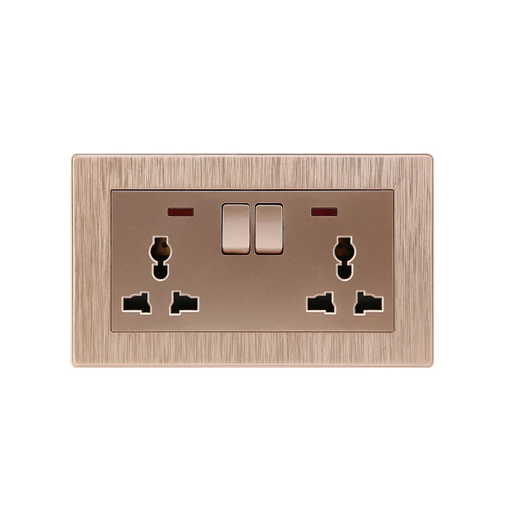
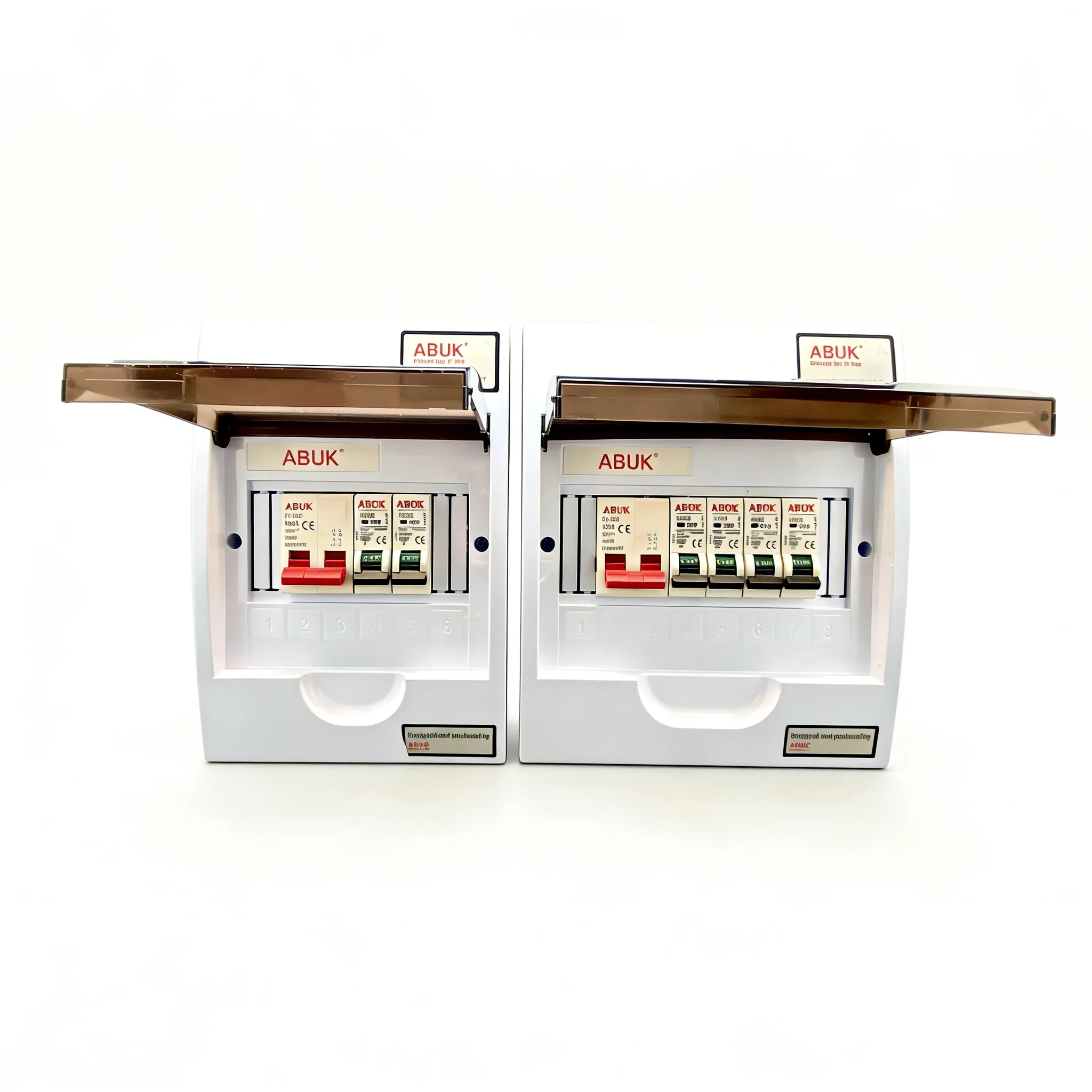
ABUK provides lighting control module interfaces and related wall-control products with CE, RoHS, and GCC documentation for specified models and markets, subject to project verification.
Frequently Asked Questions
What is a lighting control module?
It receives a control input and operates one or more lighting outputs through relays, dimming circuits, or a digital protocol.
What are common control-module problems?
Common problems include wrong protocol, excessive LED inrush, missing bus power, duplicate addresses, incompatible dimming curves, loose terminals, and overheating.
What does light control module in high voltage mode mean?
Terminology varies by manufacturer; it often means the output switches or modulates mains voltage rather than a low-voltage control pair. The manual must define the mode before wiring.
Is DALI the same as 0–10 V?
No. DALI is an addressed digital protocol, while 0–10 V is an analog level. They require different drivers and commissioning methods.
How many lights can one module control?
The limit depends on relay current, LED inrush, dimming-channel capacity, and protocol limits. A DALI line can address up to 64 control gear devices, but electrical loading still applies.
How should a buyer select a light control module?
The buyer should match supply, load type, protocol, driver list, channel count, environment, and test documentation. ABUK’s light control module related portfolio can be reviewed against the project schedule.
References
- DALI Alliance — DALI-2 certification and interoperability
- IEC Webstore — IEC 62386 and IEC 60669 standards
- European Commission — Low Voltage Directive
- European Commission — RoHS Directive
The useful lesson is that lighting control is a chain, not a box: the sensor, logic, protocol, driver, load, and compliance file must all describe the same system.
ABUK builds control and wiring-device solutions for that moment. Share the luminaire schedule and destination standard through the lighting control module project contact channel for a model-specific review.