
 Wenzhou Lita Electric Co., Ltd.
How to Connect Ethernet Cable to Wall Socket?
Connecting a computer to an existing network outlet and terminating the cable behind a new outlet are different jobs. A patch cable plugs into the front; the permanent cable normally terminates on the rear of a compatible jack. Confusing those jobs can lead to a neat-looking installation that fails testing or has no network service. The less obvious trap is a split pair: pin-to-pin continuity can pass even though the conductors no longer form the correct twisted pairs. This guide explains how to identify the connection, choose the jack, terminate it consistently, and verify the result before closing the faceplate. It also separates data wiring from mains electrical work.
The short answer is to plug a suitable Ethernet patch cable into an existing ethernet wall socket and connect the other end to the device. For an unterminated in-wall cable, fit a compatible keystone jack, place its eight conductors according to the jack’s T568A or T568B label, terminate them using the specified method, and test the link. Use the same scheme at both ends of an ordinary straight-through permanent link. Disconnect the cable from active equipment, including any PoE source, before termination. First confirm where the far end goes: a passive wall jack does not supply an Internet connection by itself.
Are you plugging into an existing socket or wiring a new one?
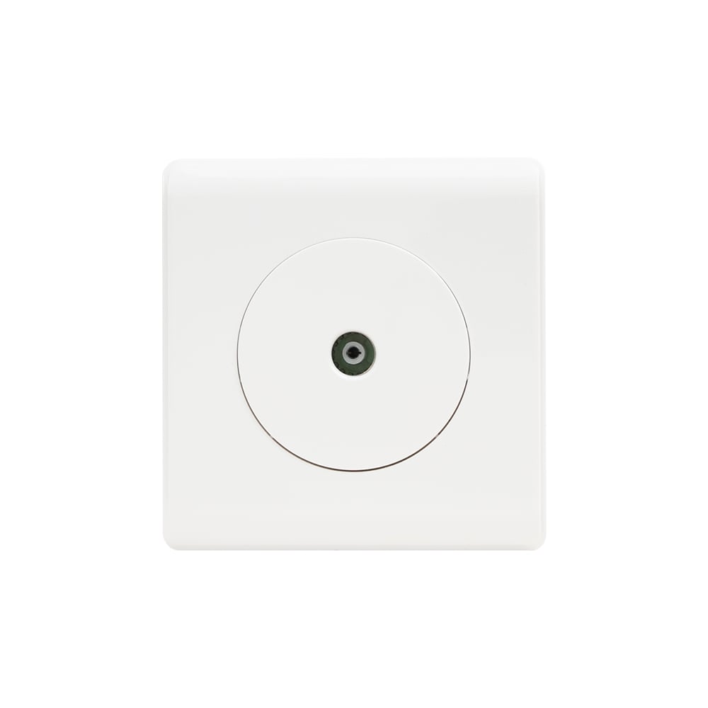
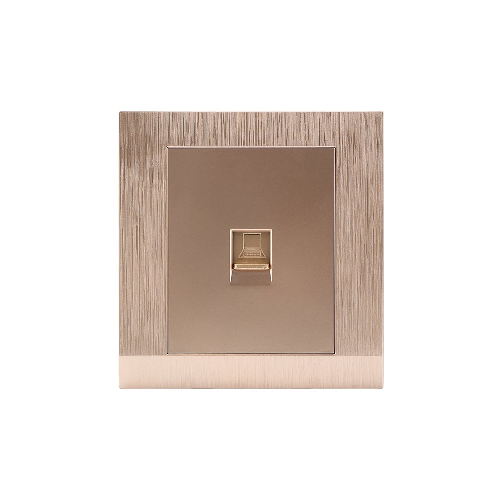
Before comparing wall socket types by appearance, identify the connector and its intended function. A finished network outlet usually contains an eight-contact modular jack, commonly called RJ45, held in a faceplate. Insert the patch-cable plug until its latch engages; do not force a telephone plug or electrical plug into it. The device at the other end of that patch cable might be a computer, access point, or another compatible Ethernet device.
Behind the faceplate, the jack is normally connected to a permanent cable that ends at a patch panel or another jack. That far end must be patched to an appropriate active network port, such as a switch or a router’s LAN port. A disconnected patch-panel port, disabled switch port, or wrong network configuration can explain a lack of service even when the outlet wiring is correct. The wall jack is a passive connection point, not a router, modem, or network configuration service.
When the cable behind the wall is still loose, the task is termination. A punchdown jack uses insulation-displacement contacts, or IDC terminals; a tool-free jack uses its own loading and closure mechanism. Follow the instructions for the actual part rather than assuming every jack takes the same tool. Manufacturer documentation, such as Leviton’s 61110-RW6 Cat 6 jack page, identifies the termination type and permitted conductor construction.
Which cable, keystone jack, and faceplate should be used?
Select a jack specified for the intended cabling system and compatible with the cable’s construction. Cat5e, Cat6, and Cat6A are category designations, not interchangeable installation instructions. A Cat6A label on one new jack does not upgrade a link containing unverified cable, connectors, or patch cords. Confirm the required category and test scope across the complete installation before purchasing replacement parts.
Check conductor size, solid versus stranded conductors, cable diameter, and shielding requirements against the jack datasheet. For example, Leviton’s 61110-RW6 page lists 26 to 22 AWG solid conductors and 24 to 22 AWG stranded conductors, with a separate limited retermination provision for 26 AWG stranded conductors. Those are that product’s limits, not a universal allowance for every IDC jack. A stranded patch cord should not be punched into a contact intended only for solid conductors.
The keystone opening and retaining mechanism must also fit the faceplate; the back box needs room for the jack and a cable bend that follows the cable manufacturer’s instructions. For shielded systems, use the specified shielded connecting hardware and follow the system’s bonding requirements. Do not trim a separator, foil, drain wire, or jacket farther than the component instructions allow just to make the assembly fit.
A suitable ethernet wall socket is therefore a matched cable-and-jack assembly, not merely a plate with the right-shaped opening. Keep the product datasheet and installation sheet with the cable schedule so that a replacement installer can identify what was approved.
How do T568A and T568B determine the wire positions?
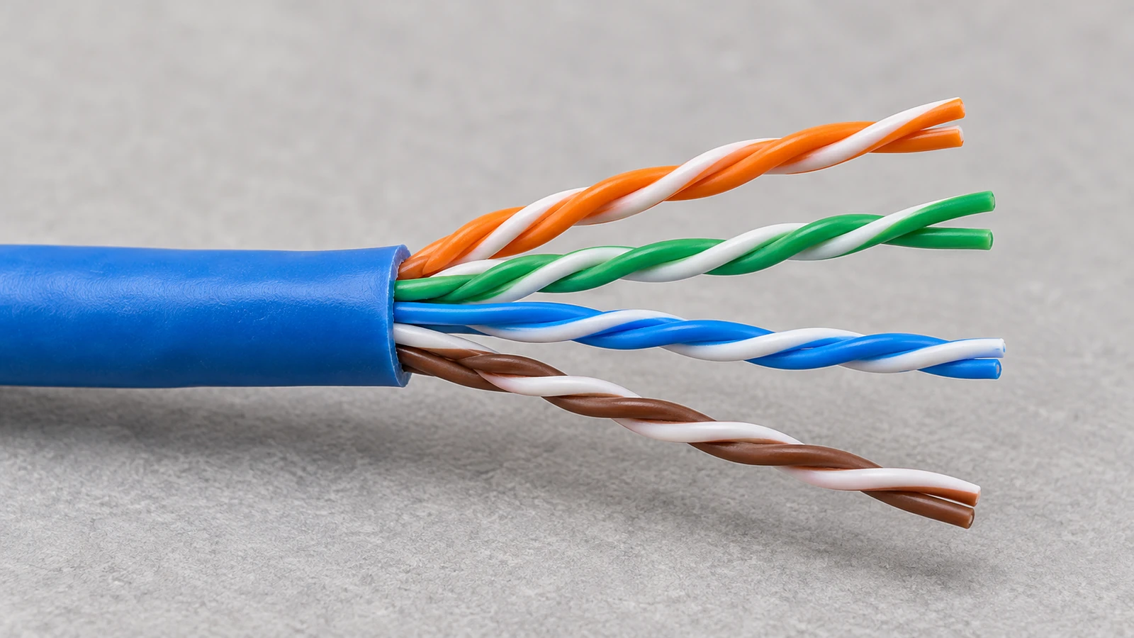
T568A and T568B define conductor-to-contact assignments for four-pair cabling. The orange and green pairs exchange positions; the blue and brown pairs keep the same assignments. For a conventional straight-through permanent link, follow the project’s specified scheme and match the far-end termination. Neither scheme is a shortcut to a higher cable category.
The following table identifies the numbered contacts at the connector interface. It is not a left-to-right punchdown diagram for the back of a jack. As Fluke Networks’ T568A versus T568B reference explains, rear contact layouts vary by manufacturer because the internal connections route conductors to the correct front contacts. Use the A or B color label on the actual jack.
| Contact | T568A conductor | T568B conductor |
|---|---|---|
| 1 | White/green | White/orange |
| 2 | Green | Orange |
| 3 | White/orange | White/green |
| 4 | Blue | Blue |
| 5 | White/blue | White/blue |
| 6 | Orange | Green |
| 7 | White/brown | White/brown |
| 8 | Brown | Brown |
The physical pair groups are contacts 1-2, 3-6, 4-5, and 7-8. In particular, contacts 3 and 6 belong together even though they are not adjacent in the numerical sequence. Preserving those pair relationships is essential: lining up eight wires in numerical order on an unfamiliar IDC block can create split pairs.
Record whether T568A and T568B labeling has been interpreted correctly before repeating the same termination on multiple outlets. One confirmed sample, checked against both the jack label and far-end wiring, is more useful than copying an unverified color photograph across an entire project.
How is the permanent cable terminated without damaging the pairs?
- Identify and disconnect the cable. Trace both ends and unplug it from the switch, router, injector, or other active equipment before working. Disconnect any PoE source; do not treat a cable feeding a powered access point or camera as an unpowered loose wire.
- Prepare only the required jacket length. Use a suitable cable stripper without cutting the conductor insulation. If a conductor has been nicked, remove the damaged section and prepare an undamaged end rather than hiding the defect inside the box.
- Route each pair using the selected jack label. Keep each twisted pair together until the routing instructions require separation. Maintain twists as close to the termination as the jack permits; follow its specified untwist and jacket-removal limits rather than applying a guessed universal dimension.
- Seat and terminate the conductors. For a punchdown jack, use its specified blade or tool and orient any cutting edge toward the waste end. For a tool-free design, follow the conductor-loading sequence and close the mechanism fully. IDC contacts displace insulation; do not pre-strip individual conductors unless that jack’s instructions specifically require it.
- Secure, label, and test before final assembly. Fit any required cap or strain relief, ensure the cable is not pinched, and identify the outlet and far end. Test before clipping the jack into the faceplate, then check again after mounting if the cable has been moved significantly.
Do not use the faceplate screws to force a bulky cable into an undersized box. The visible plate can look finished while the cable is sharply bent, a cap is displaced, or an IDC connection is stressed. Mechanical fit and electrical pair integrity must both survive the final mounting operation.
Which tests confirm the socket works, and which do not?
Begin with a cable tester and its remote unit at the far end. Check for opens, shorts, reversed conductors, crossed pairs, and split pairs. Verify that the selected tester actually detects split pairs: some simple LED continuity testers report pin-to-pin connection without assessing whether each circuit follows a physical twisted pair.
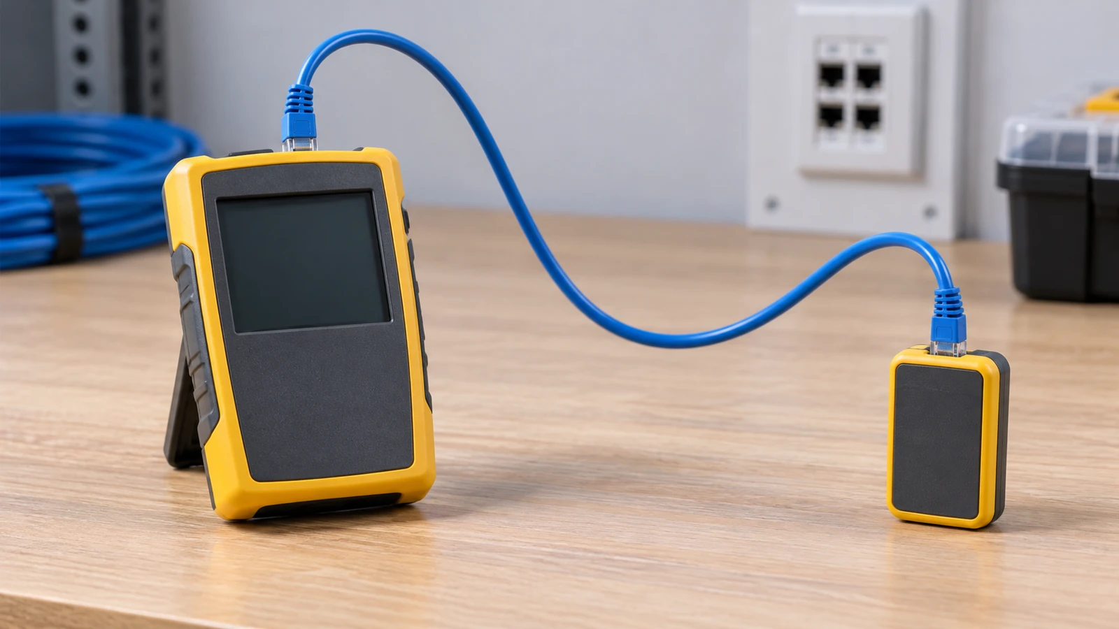
Fluke Networks’ wire-map explanation describes why a split pair can pass simple DC continuity yet fail near-end crosstalk testing. This is why a row of eight successful continuity indications is not proof of the cabling’s category performance.
| Check | What it establishes | What it does not establish | Practical use |
|---|---|---|---|
| Simple DC continuity | An electrical path between contacts; fault detail depends on the tester | Correct physical pairs or transmission performance | Basic preliminary check; do not accept it as the only handover evidence |
| Wire map with split-pair detection | Conductor assignments and supported wiring-fault checks | Full category or class compliance | Find termination mistakes before commissioning |
| Application qualification | Whether the tested link supports the application assessed by that instrument | Full standards-based category certification | Assess an existing link or troubleshoot application suitability |
| Cabling certification | Measured pass/fail against selected category or class limits and link configuration | Correct switch settings, Internet availability, or every device fault | Contractual acceptance where the project or system warranty requires it |
| Live device connection | Whether the connected equipment establishes service under the present configuration | A complete cabling test report | Final functional check after the passive cable tests pass |
Use a certifier with the correct permanent-link or channel setup when the project requires category or class acceptance. Relevant structured-cabling specifications include the ANSI/TIA-568 and ISO/IEC 11801 families; use the edition and limits named in the contract, not an older article’s revision by default. Fluke Networks’ verification, qualification, and certification guide distinguishes these three levels of evidence.
Save the outlet identifier, cable and jack details, wiring scheme, selected test limit, instrument information, and results. A certification measurement is not a blanket product approval or an electrical-safety certificate. Missing or inappropriate test records can create retesting costs and prevent acceptance under a contract or a manufacturer’s warranty terms.
After passive testing, reconnect the far end to the intended active port and check the actual application. If a correctly tested outlet still has no service, investigate the patching, switch-port state, device configuration, and network settings. Repeatedly punching down an already verified jack will not fix a disabled network port.
What should buyers check when power and network outlets share a location?
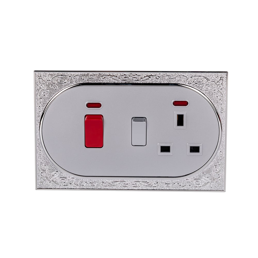
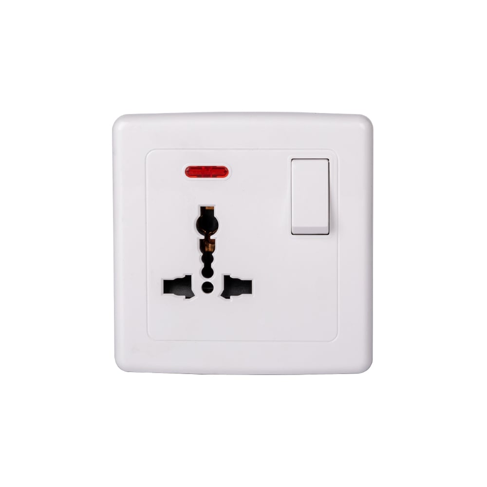
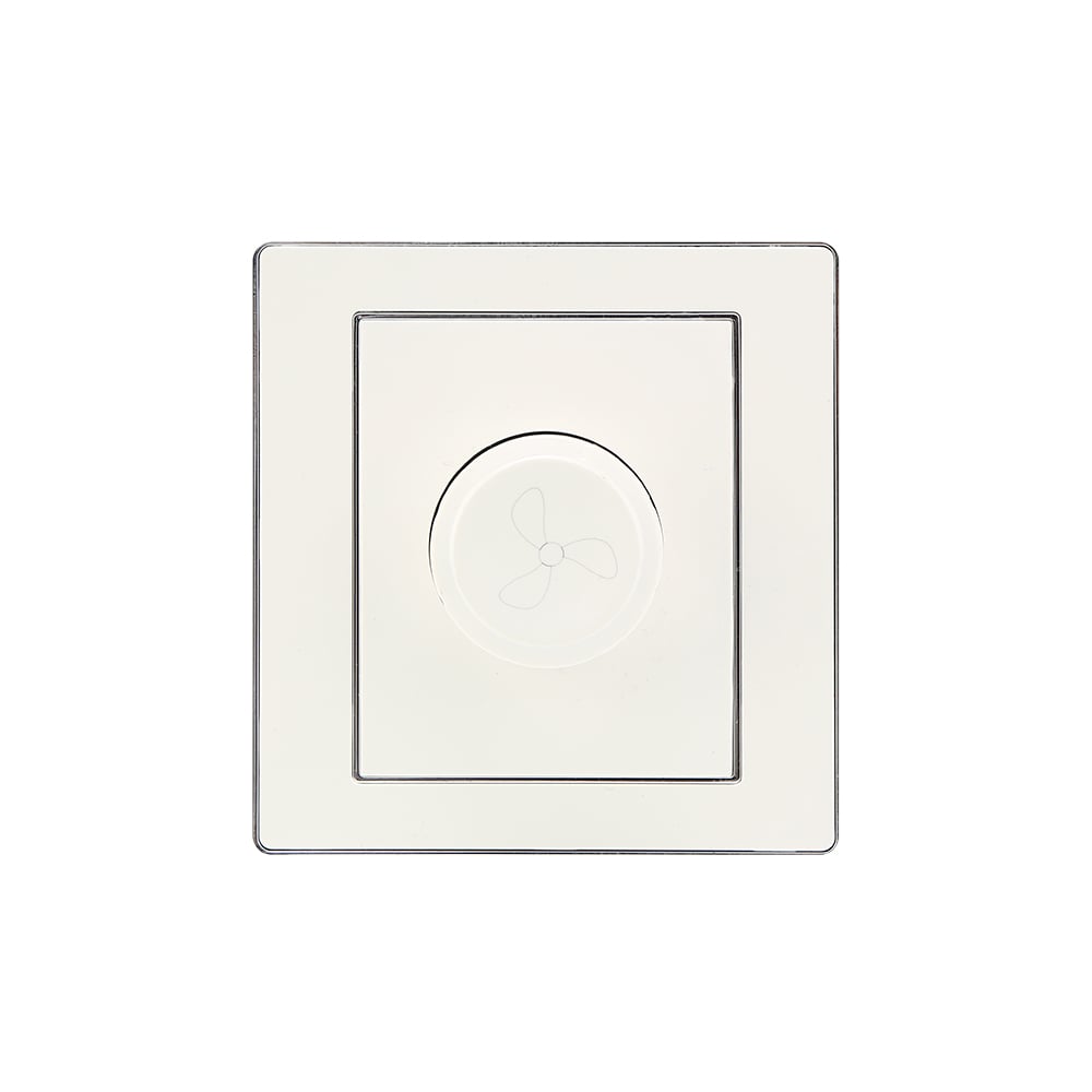
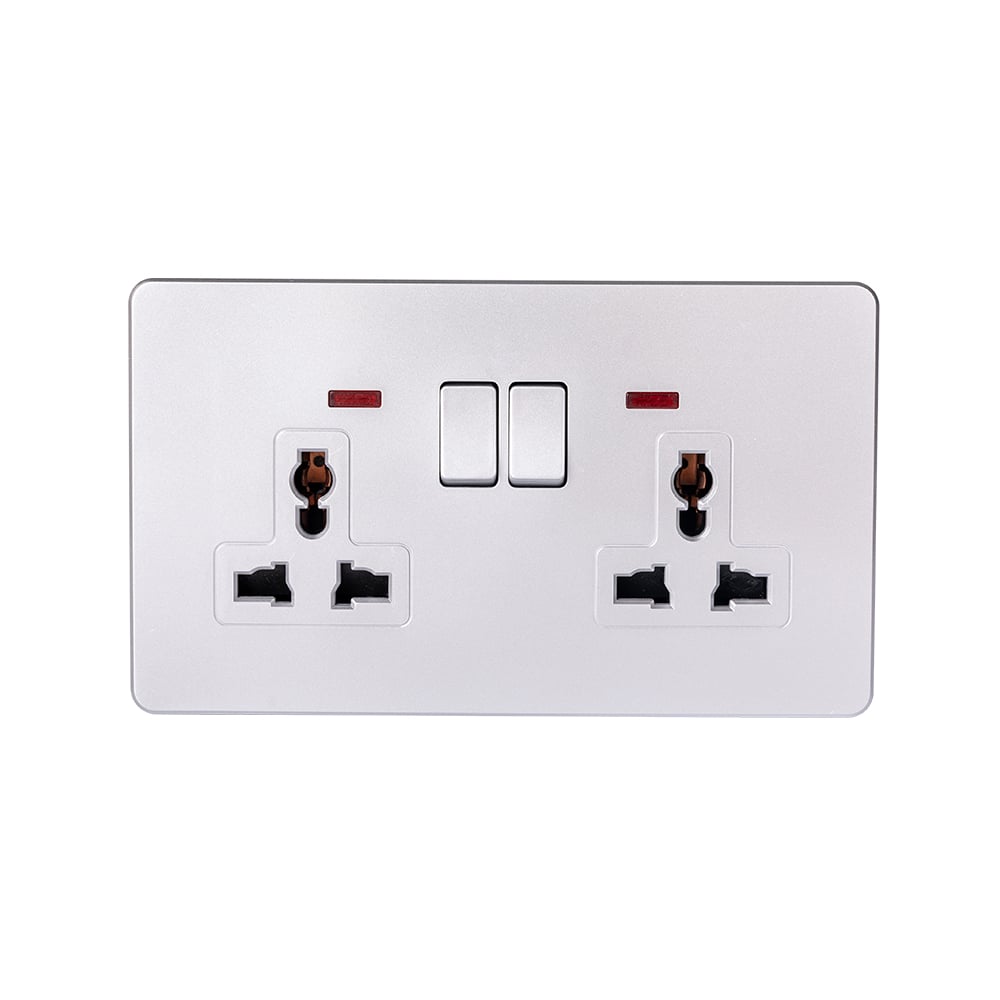
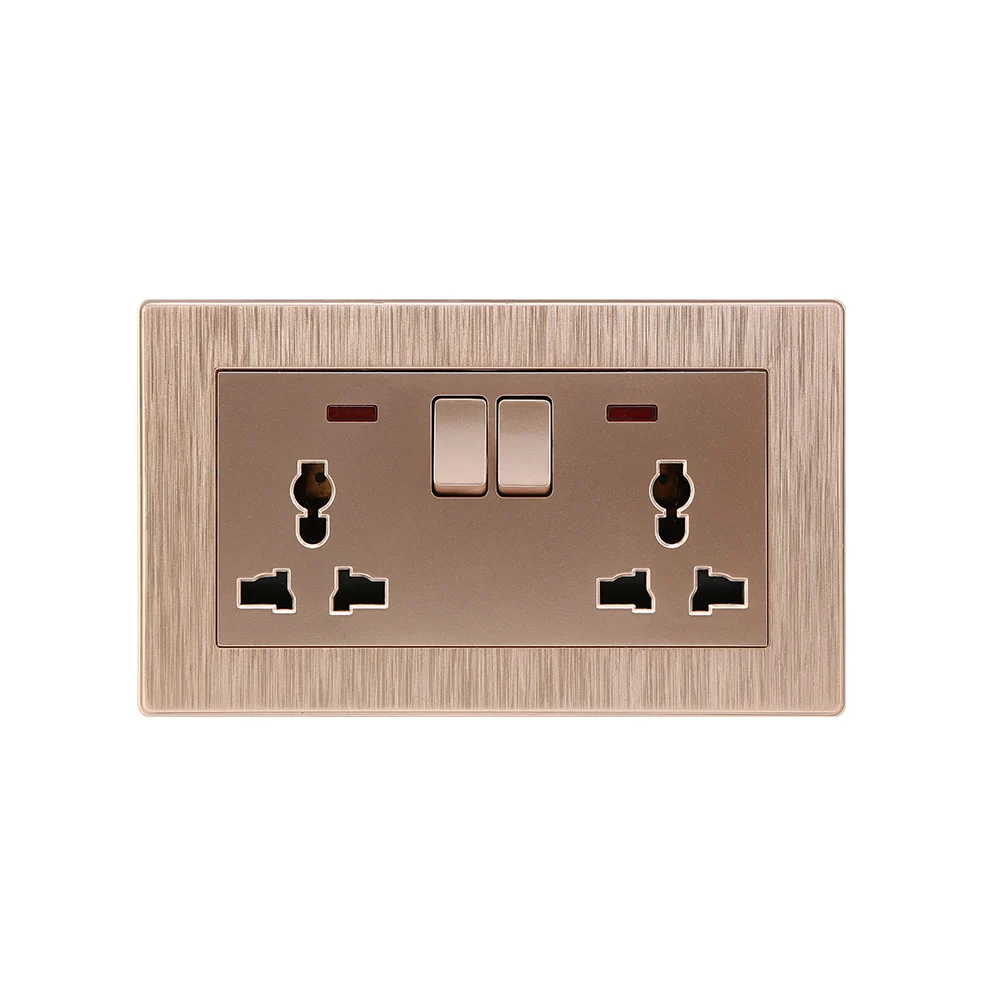
When coordinating different wall socket types at one location, distinguish their functions before matching appearance. An ethernet wall socket carries a data connection; a mains receptacle supplies electrical power. A wall socket dimmer switch controls a compatible lighting load, not Ethernet traffic. An outdoor wall socket’s power-outlet enclosure rating does not establish that a nearby network jack is suitable for weather exposure.
Do not share a mains wiring box with network terminations unless an approved assembly provides the required segregation and the installation complies with the applicable local wiring rules. A matching plate, spare opening, or improvised divider does not prove approval. Where mains devices need alteration, use a qualified electrical installer and the required isolation procedure rather than extending this data-termination method to power wiring.
For a coordinated fit-out, use the following procurement sequence:
- Specify data category, conductor construction, shielding, and test requirements independently of the power-outlet schedule.
- Approve the exact jack, faceplate, and back-box fit before ordering the complete quantity.
- Confirm cable routing and any approved power/data segregation with the responsible installer.
- Include labels, test records, and the active-port patching plan in handover, rather than budgeting only for visible plates.
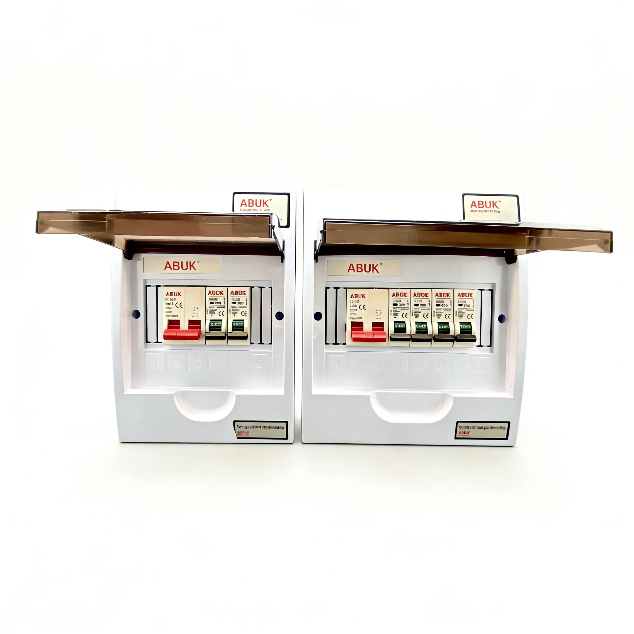
ABUK’s published Series 10 power sockets and switches can be reviewed for the electrical-device side of a room specification; that listing is not evidence of a Cat6 Ethernet jack. Buyers comparing wall socket types or specifying a china wall socket should keep mains interface, supply, and approval checks separate from the network termination plan. Matching finishes does not make the two systems electrically interchangeable.
What else should be checked before using the outlet?
How do you connect an Ethernet cable to a wall socket?
Plug a compatible Ethernet patch cable into the front of an installed network jack and connect its other end to the device. If the in-wall cable is unterminated, first fit a compatible jack, follow its wiring label and termination instructions, and test the permanent link. Confirm that the far end is patched to an active network port.
What wiring standard is used for an Ethernet wall socket?
T568A and T568B are the two familiar conductor-assignment schemes. Match the project’s specification and use the same scheme at both ends of a normal straight-through permanent link. The rear IDC layout is manufacturer-specific, so follow the jack label rather than placing wires according to a front-contact drawing.
Can a wall socket combine Ethernet and power?
A purpose-designed assembly may place data and mains outlets together, but it must provide the approved separation required for that installation. Do not add a network jack to an ordinary mains box without verified approval and segregation. PoE over compatible Ethernet cabling is different from routing mains conductors through a data jack.
How do I test a newly terminated network socket?
Connect a cable tester and remote at the two ends, then verify the wire map with a tool that detects split pairs as well as opens, shorts, and incorrect assignments. Use category or class certification when the specification requires it; continuity alone is insufficient. Finally reconnect the active equipment and check service on the intended network.
Which sources support the wiring and testing guidance?
Source pages were checked on October 8, 2026. This guide interprets public manufacturer documentation; it does not report ABUK network testing, an installation case study, or a verified ABUK Ethernet product offering.
- Fluke Networks: Differences Between Wiring Codes T568A vs T568B, page dated January 29, 2014; conductor assignments and manufacturer-specific rear jack layouts.
- Leviton: EXTREME Cat 6 QUICKPORT Jack, 61110-RW6, current product page; termination type, conductor compatibility, and installation-document links.
- Fluke Networks: Wire Map Testing: It’s Not All About Color, September 6, 2018; wiring faults and the continuity limitation of split pairs.
- Fluke Networks: Importance of Cable Verification, Qualification and Certification, January 23, 2019; test scope and standards-based acceptance. Its historical standards examples do not select the edition for a new project.
What makes a completed wall connection dependable?
A dependable wall connection needs more than a plug that fits or eight continuity lights. First establish whether the task is patching into a finished outlet or terminating a permanent cable, then confirm the cable, jack, conductor construction, and far-end destination. Follow one wiring scheme, preserve the pairs according to the jack instructions, and select testing that matches the evidence the project actually requires. Do not skip PoE disconnection or approved mains/data segregation for the sake of a matching faceplate. An ethernet wall socket can pass its passive-cabling tests and still lack service until it is patched to correctly configured active equipment. For the separate electrical-device schedule, review ABUK’s wiring-device catalogue and contact ABUK with the power-outlet, mounting, and destination-market requirements; obtain verified network-component documentation from the relevant supplier.