
 Wenzhou Lita Electric Co., Ltd.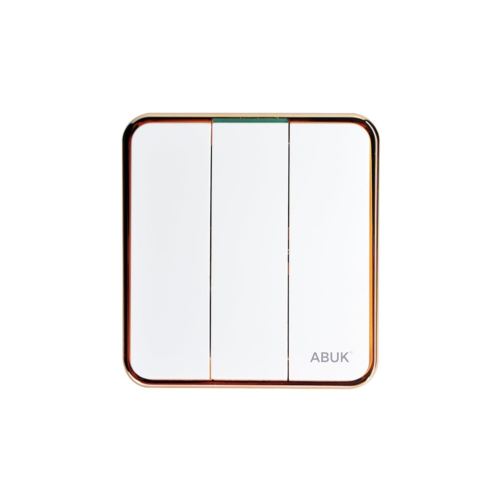




How to Wire a Switch Outlet Combo?
When an electrical contractor in Austin encountered a cramped utility-room box, he watched a short tutorial, installed a combination device, and confidently restored power. The breaker tripped immediately; after rewiring, the receptacle worked only when the light was on, and the inspection required another visit. The device was not faulty—the installer had misunderstood the common feed, switched leg, neutral, and removable tab. The real question was: how should a switch outlet combo be wired for the intended function?
Summary: A switch outlet combo places a switch and receptacle on one yoke, but its wiring depends on whether the receptacle remains constantly energized or is controlled by the switch. A typical 15 A, 125 V device needs an identified line conductor, switch output, receptacle neutral, equipment grounding conductor, correct tab configuration, adequate box fill, and the manufacturer’s terminal torque. Qualified installation and testing should follow NEC, UL 20, and UL 498 requirements.
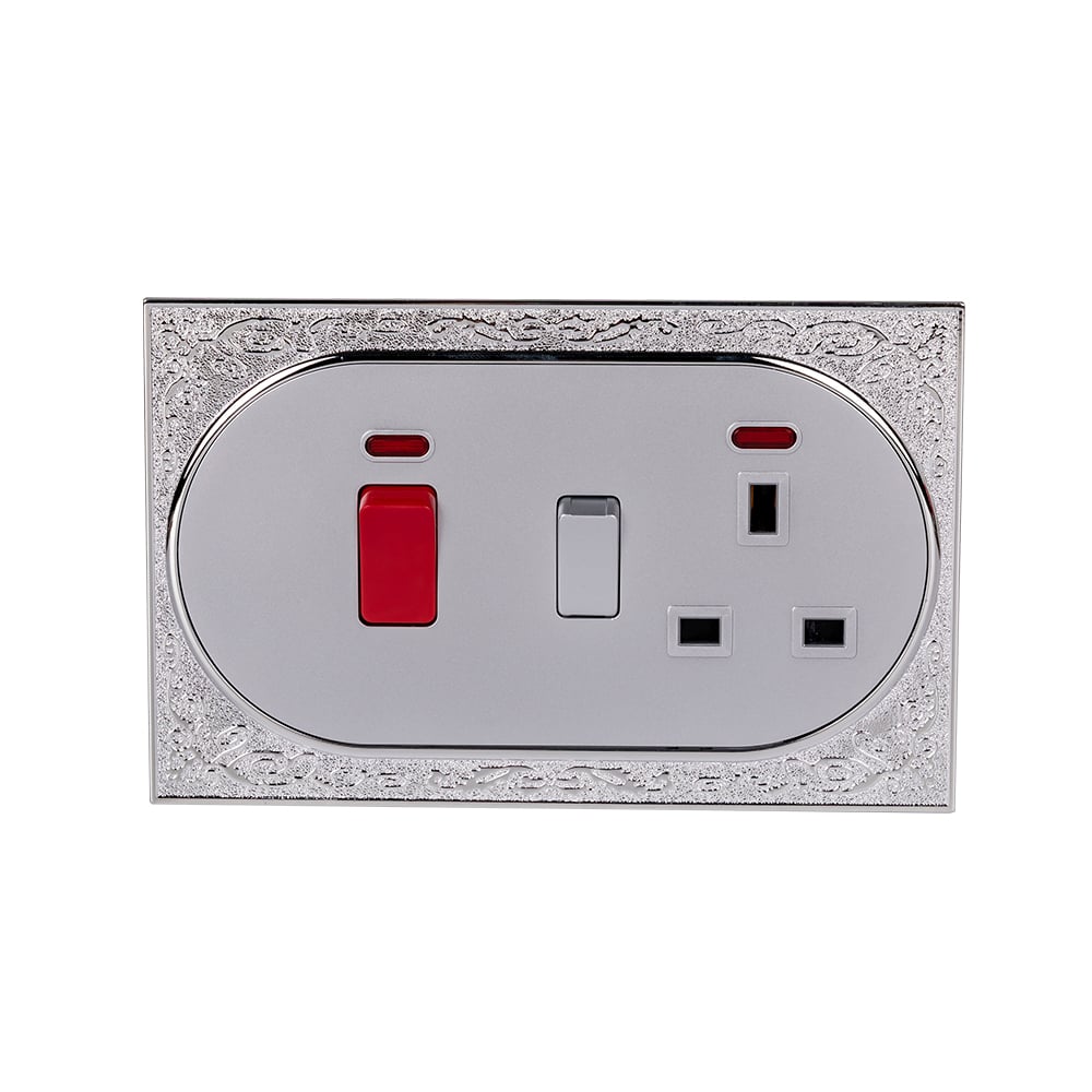
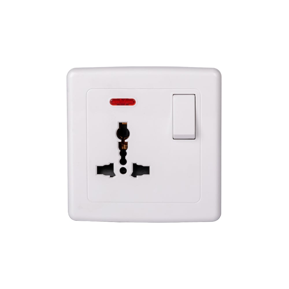
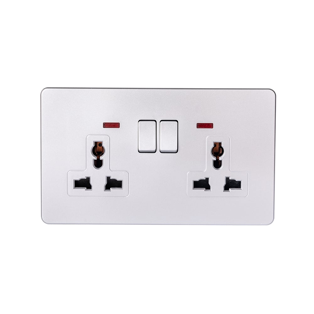
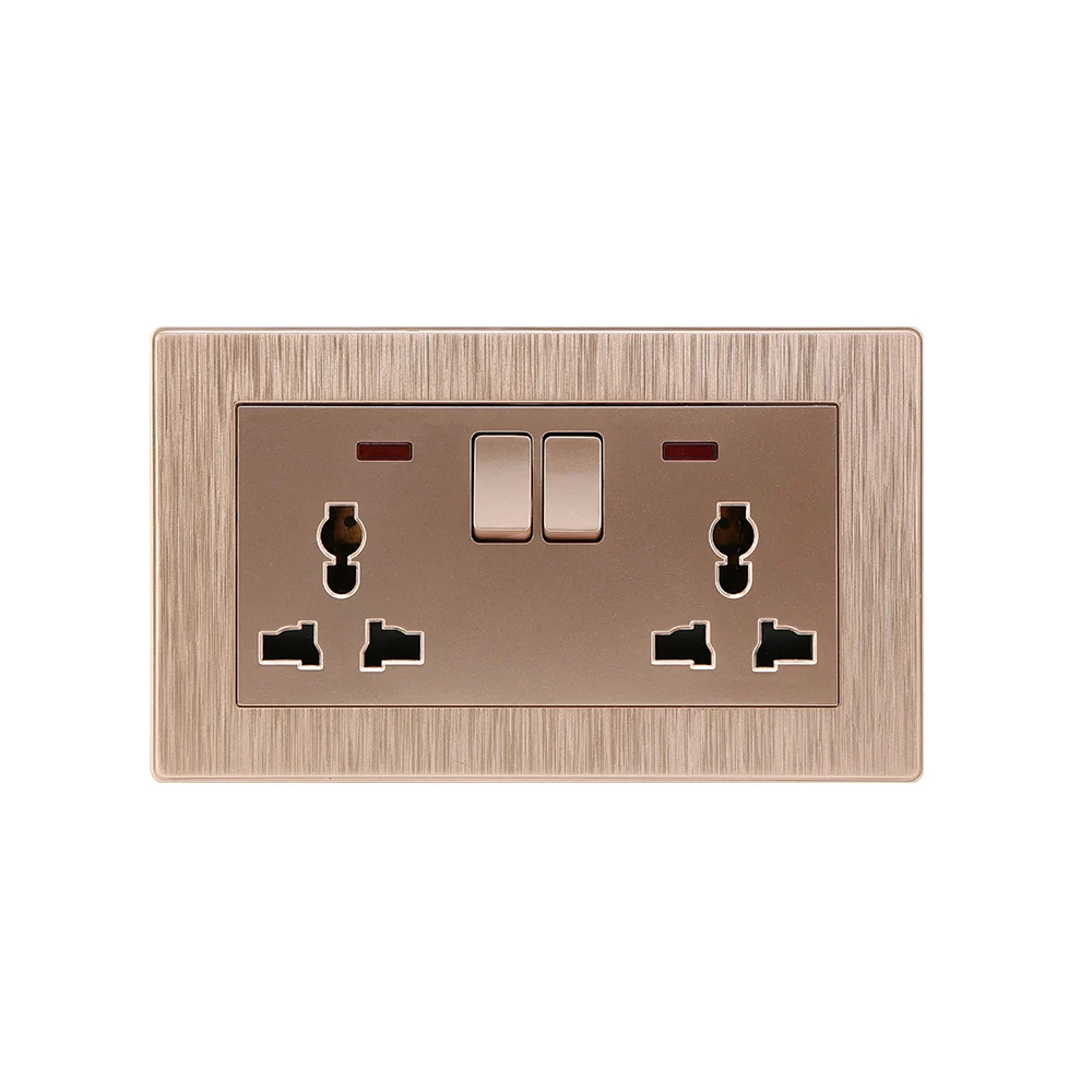
A light switch and plug combination saves wall space by integrating two functions in one device. It does not eliminate conductors: the receptacle still needs line and neutral, the switch still needs a feed and switched output, and the metal mounting yoke or grounding terminal must be bonded as required. Because terminal layouts vary, a generic color diagram should never replace the model-specific instructions.
Which Terminals Does the Combination Device Use?
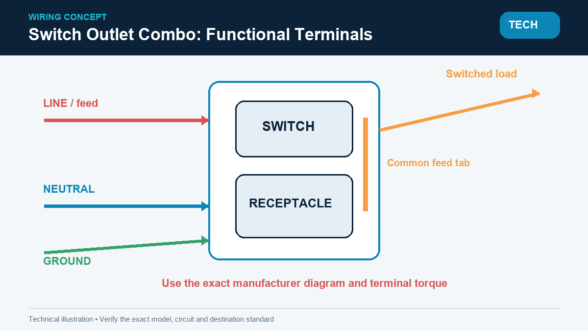
A common 15 A, 125 V combination device has a receptacle section evaluated to UL 498 and a switch section evaluated to UL 20. The line side may include a common tab feeding both sections; the neutral terminal serves the receptacle, while a separate terminal sends switched power to the light or fan. Grounding connects to the green terminal and approved box-bonding arrangement. Terminal color is helpful but not universal, so markings such as LINE, NEUTRAL, COMMON, and LOAD control the interpretation.
How Is the Intended Function Chosen?
- Always-hot receptacle: the incoming line feeds both sections, while the switch sends power only to the connected load.
- Switched receptacle: the switch output feeds the receptacle; this arrangement must be explicitly supported by the device diagram.
- Separate feeds: removing a factory tab may isolate the sections, but only when the listing and instructions permit it; multiwire branch-circuit and disconnect rules may then apply.
The installer must identify conductors rather than assume black is always line or white is always neutral. NEC 404.2(C) also requires a neutral at many switch locations, subject to its conditions and exceptions; existing wiring must be evaluated against the adopted code edition.
What Is the Safe Wiring Workflow?
- A qualified person de-energizes the circuit, applies appropriate lockout controls, and verifies absence of voltage with a properly rated tester.
- The feed, neutral, switched leg, grounding path, breaker rating, conductor size, and box fill are identified before removing the old device.
- The desired always-hot, switched, or split-feed function is matched to the exact manufacturer diagram; any tab change is made only as instructed.
- Conductors are terminated within the listed wire range and torque, then folded without damaging insulation or overcrowding the box.
- After re-energization, polarity, grounding, switch operation, receptacle voltage, and required GFCI/AFCI protection are tested and documented.
Where Do Hidden Costs Appear?
If 100 guest rooms require a 20-minute callback at USD 45 per hour because the receptacle was accidentally switched, labor reaches USD 1,500 before access, retesting, and room downtime. A combination device may reduce one wall opening, but undersized boxes, missing neutrals, tab errors, and unclear labels can erase the hardware saving.
Switch and Receptacle Function Comparison
| Configuration | Receptacle state | Key conductor need | Common risk | Best use |
|---|---|---|---|---|
| Shared feed | Always energized | Line, neutral, switched leg, ground | Line/load confusion | Bathrooms and utility rooms |
| Switched receptacle | Controlled by switch | Switch output to receptacle | Unexpected loss of charging power | Portable lamps |
| Separate feeds | Project-defined | Listed isolation and disconnect strategy | Tab and multiwire errors | Special renovations |
| Separate devices | Independent | Larger box and more wall space | Higher installation footprint | High-service locations |
Application Matrix
| Location | Design question | Additional protection | Standards signal |
|---|---|---|---|
| Bathroom | Accessible switch and constant receptacle? | GFCI and location clearances | NEC 210.8, 404 |
| Kitchen | Countertop circuit permitted? | GFCI/AFCI as adopted | NEC 210, 406 |
| Hotel room | Master-control or local feed? | Project energy-control logic | IEC/NEC by market |
| Renovation | Is neutral present and box deep enough? | Existing grounding evaluation | NEC 314, 404 |
Standards and Compliance
- UL 20: construction and performance requirements for general-use snap switches.
- UL 498: attachment-plug and receptacle safety requirements.
- NFPA 70 (NEC): conductor, box fill, grounding, switching, receptacle, GFCI, and AFCI installation rules.
- CE, RoHS, and GCC/GSO: relevant documentation must match the destination configuration and exact model; these marks do not replace a required UL/NEMA evaluation in North America.
Incorrect combinations can create shock exposure, reversed polarity, uncontrolled loads, nuisance trips, or failed inspections. The commercial consequence is usually rework across many identical rooms rather than a single failed device.
Selection and Installation Guide
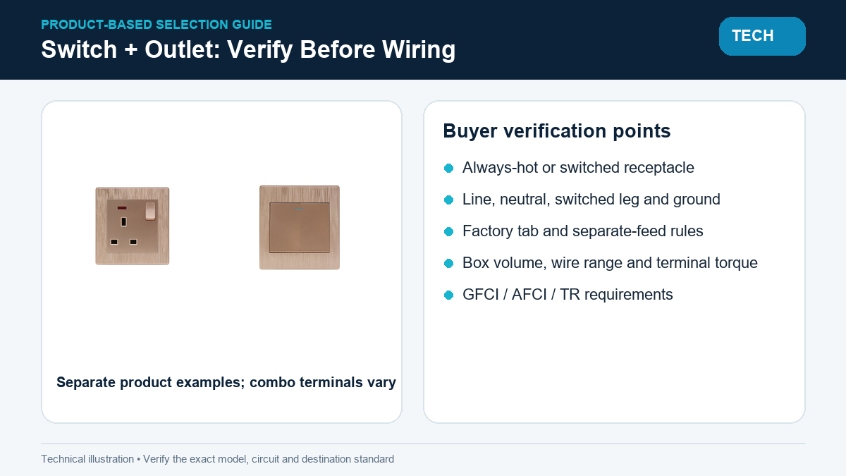
- Define whether the receptacle is always hot, switched, or separately fed.
- Confirm 15/20 A rating, voltage, plug configuration, terminal wire range, and box depth.
- Specify GFCI, AFCI, tamper-resistant, or weather-resistant features where required.
- Use model-linked diagrams and terminal torque; never copy another brand’s tab logic.
ABUK provides switch outlet combo and related wall-device configurations with CE, RoHS, and GCC documentation for specified models and markets, subject to project-level verification.
Frequently Asked Questions
How does a switch outlet combo work?
The receptacle and switch share one mounting yoke; a factory tab may share the line feed, while separate terminals serve neutral and the switched output.
Can any electrical wire be used when wiring a combo switch outlet?
No. Conductor material, insulation, gauge, temperature rating, and terminal compatibility must match the branch circuit, code, and device listing.
Where is a light switch outlet combo best used?
A light switch and plug combination is useful where one box must provide local switching and convenient power, such as utility rooms, bathrooms, and compact renovations.
Can a combo outlet stay on when the switch is off?
Yes, if the device supports a shared constant feed and is wired to its diagram. The switch then controls only the external load.
Does the combination device need a neutral?
The receptacle normally needs a neutral. The switch portion’s requirements depend on its technology and the installation rules, but the complete device diagram must be followed.
Can a GFCI be used with a combination device?
Yes, protection may be integral or upstream when permitted, but the protection boundary, LINE/LOAD arrangement, accessibility, and local NEC requirements must be verified.
References
- NFPA 70 — National Electrical Code
- UL 20 — General-Use Snap Switches
- UL 498 — Attachment Plugs and Receptacles
- OSHA — Electrical Safety
The lasting rule is that a combination device saves space, not engineering; every conductor and protective function still has to be accounted for.
ABUK builds coordinated wall devices for that moment. Send the box detail, load schedule, and destination standard through the electrical wiring switch outlet combo consultation channel for a model-specific review.