
 Wenzhou Lita Electric Co., Ltd.




How to Connect an Electrical Outlet
When a maintenance supervisor in Chicago encountered a dead receptacle during an office refresh, he ordered a matching faceplate and expected a quick replacement. In this hypothetical example, the new outlet still failed its checks because the incoming circuit had never been identified. The buying mistake was treating a familiar front face as a wiring specification.
Summary: Connecting an electrical outlet requires the correct device, identified conductors, secure terminations and verification before use. A common North American receptacle is rated 15A, 125V; that does not make its instructions suitable for a 230V socket elsewhere. HSE guidance requires isolation and checking that the circuit is dead before work. A competent electrician should resolve uncertain wiring rather than copy the old connections.
The useful question is not simply which wire goes where. It is whether the replacement suits the circuit, whether the existing wiring is sound, and what evidence will show that the finished connection is safe. This guide explains those decisions; it does not authorize untrained work on mains wiring.
What must be identified before an electrical outlet is connected?
An electrical outlet specification starts with the local plug system, circuit voltage, device rating and intended load. In North America, a NEMA 5-15R configuration identifies a common grounding receptacle rated 15A, 125V. The voltage marking is the device rating; nominal branch-circuit supply is normally 120V. Neither the shape nor the rating establishes the correct wiring method by itself.
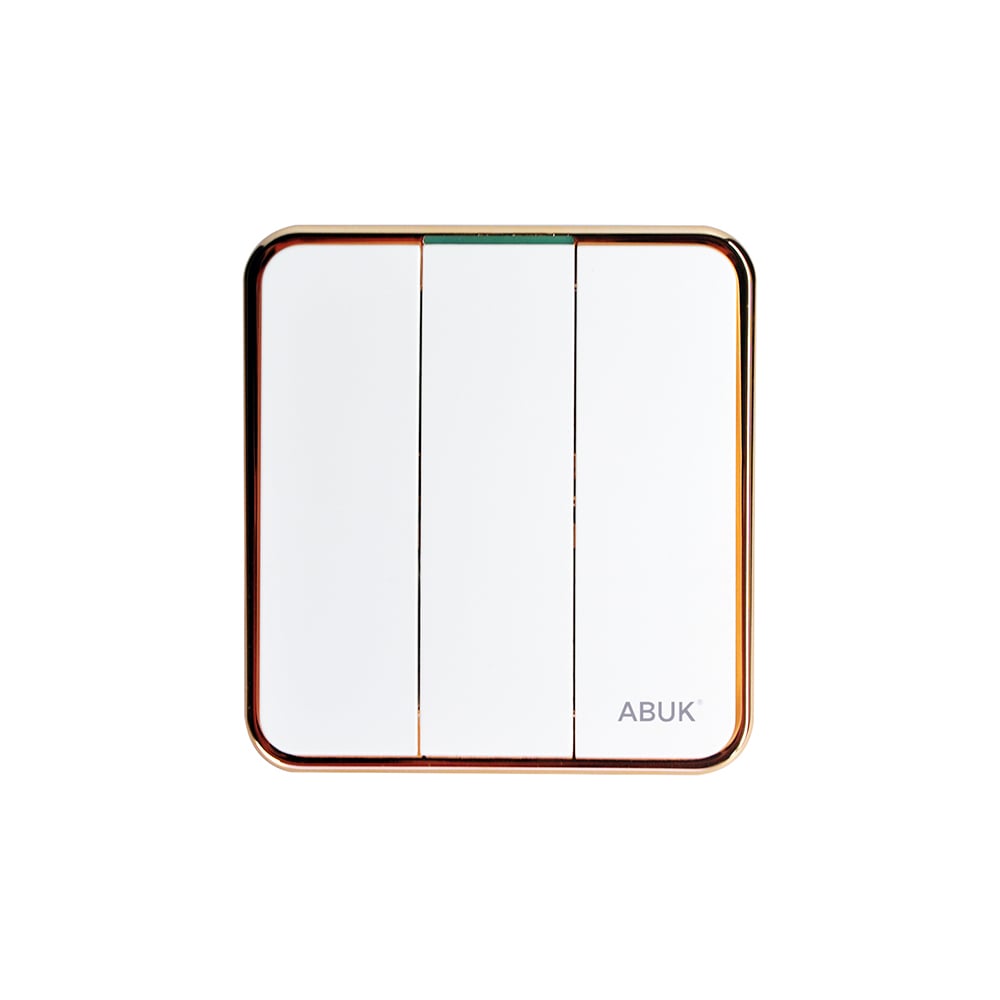
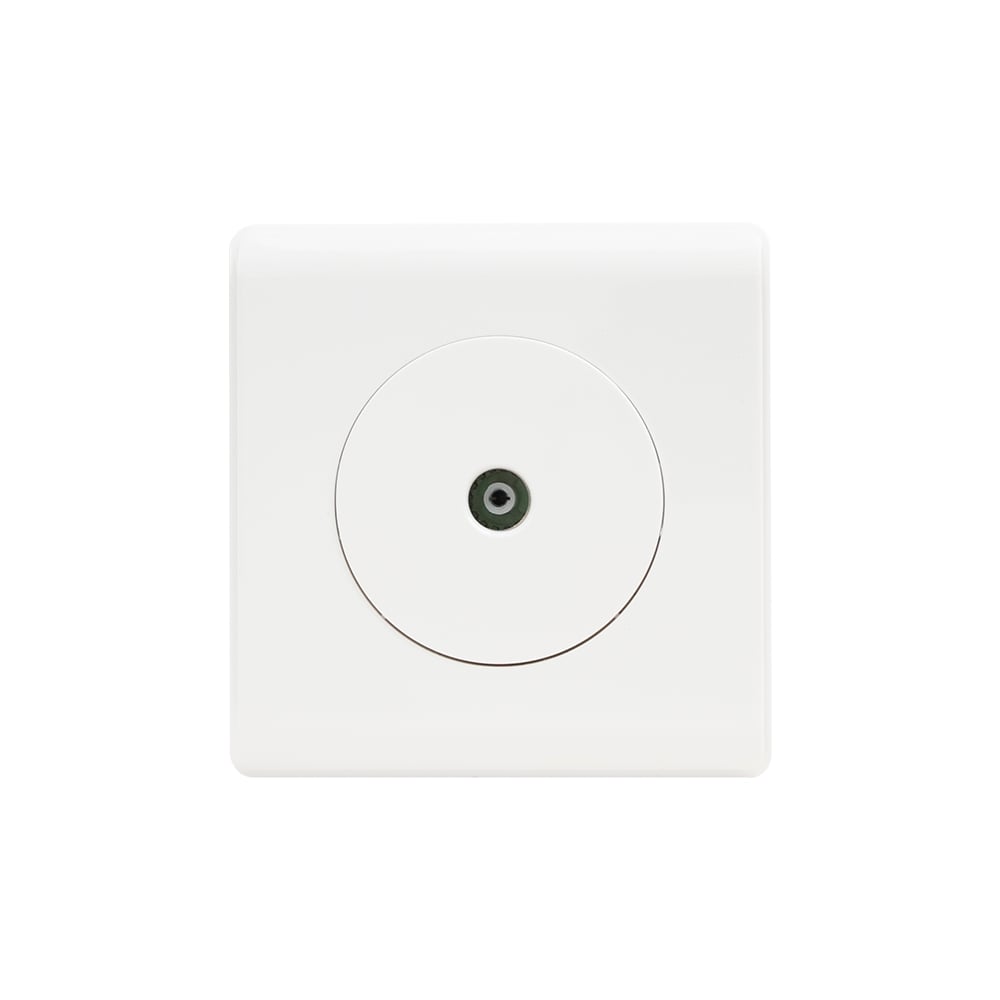
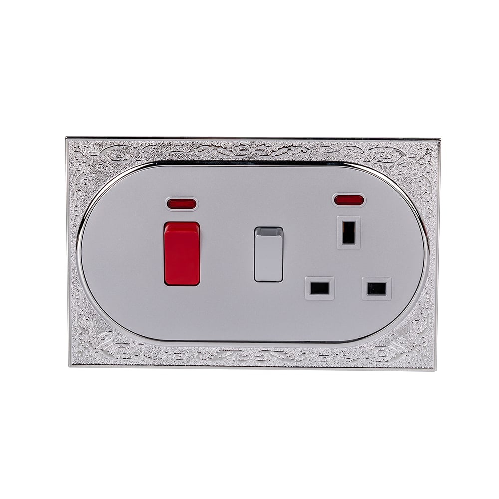
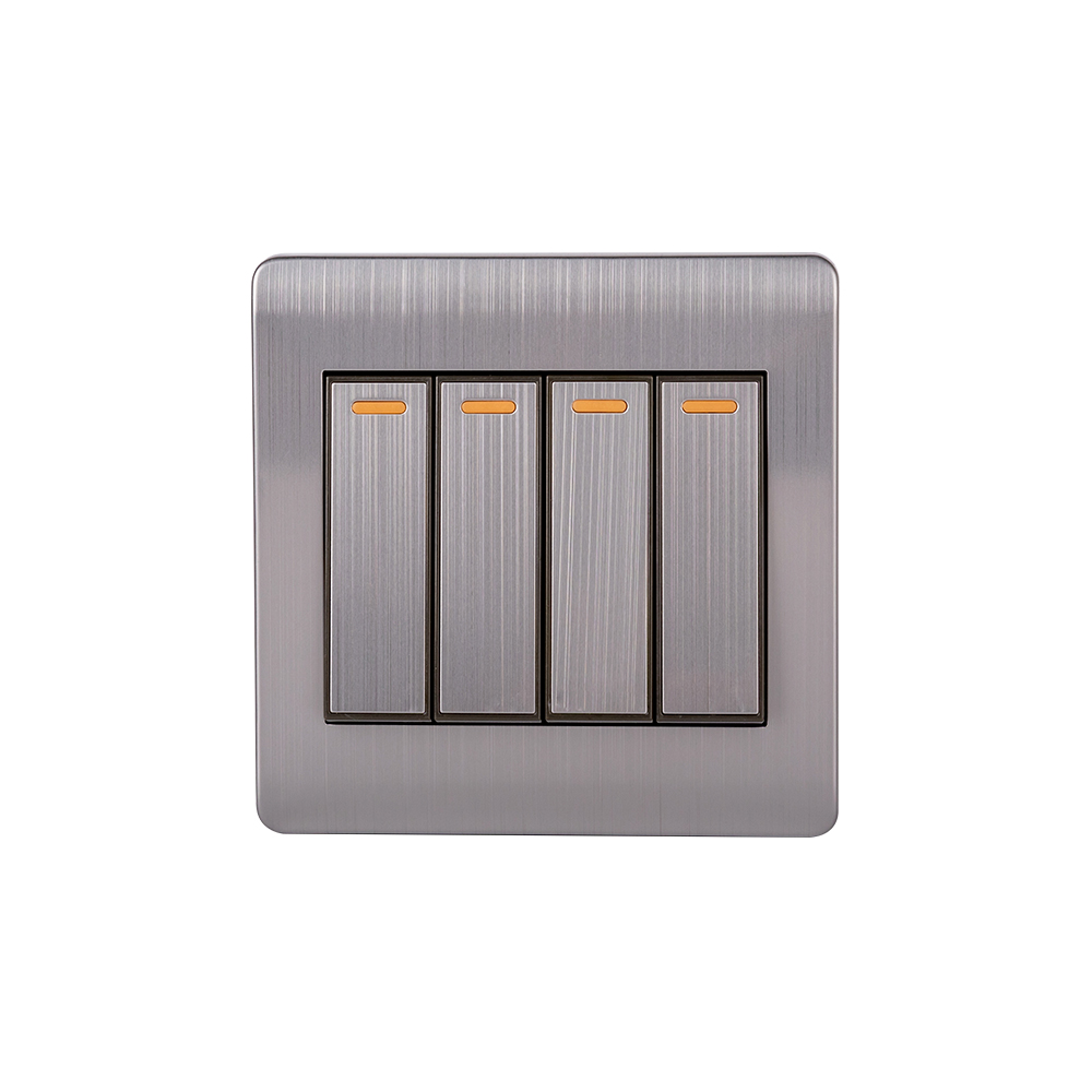
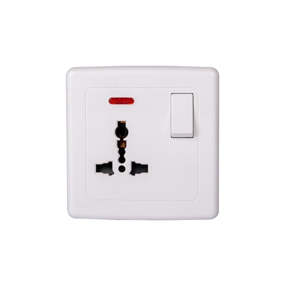
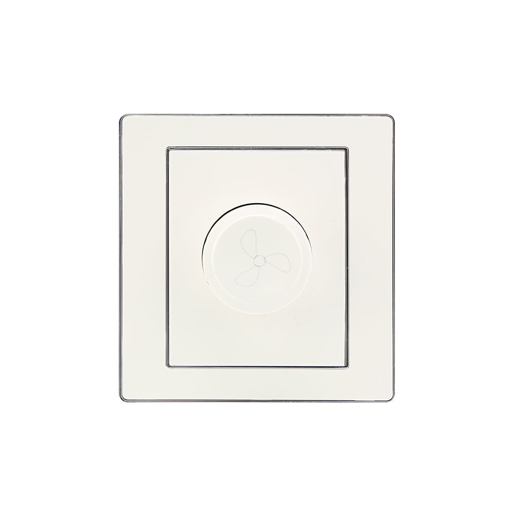
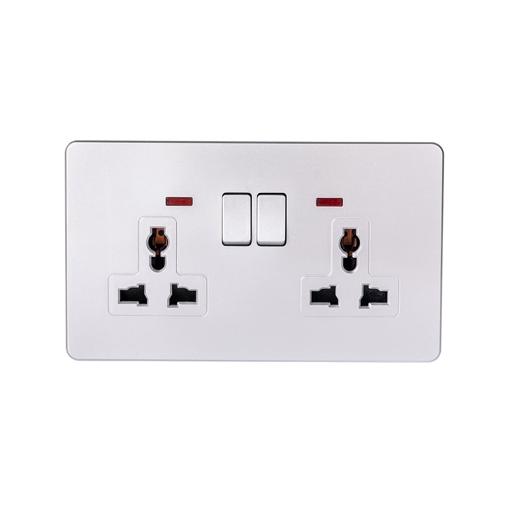
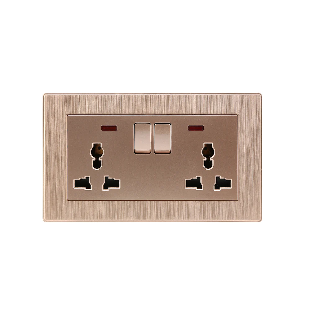
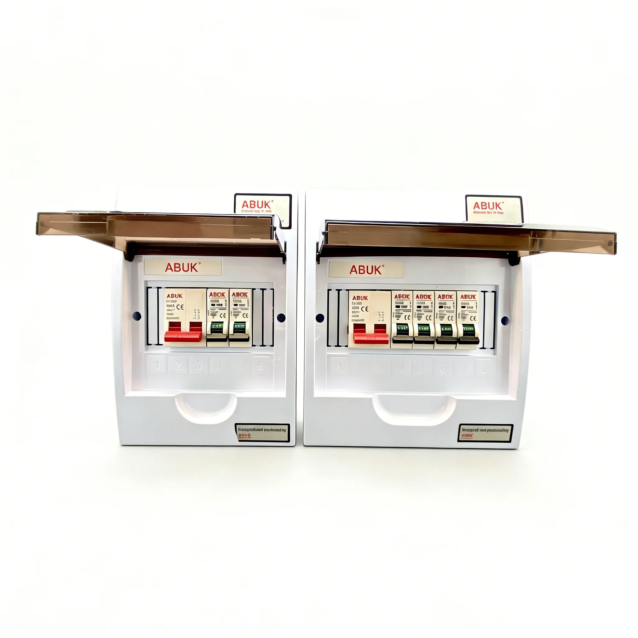
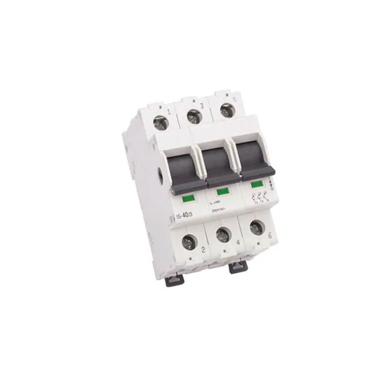
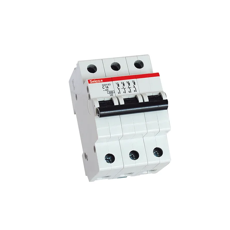
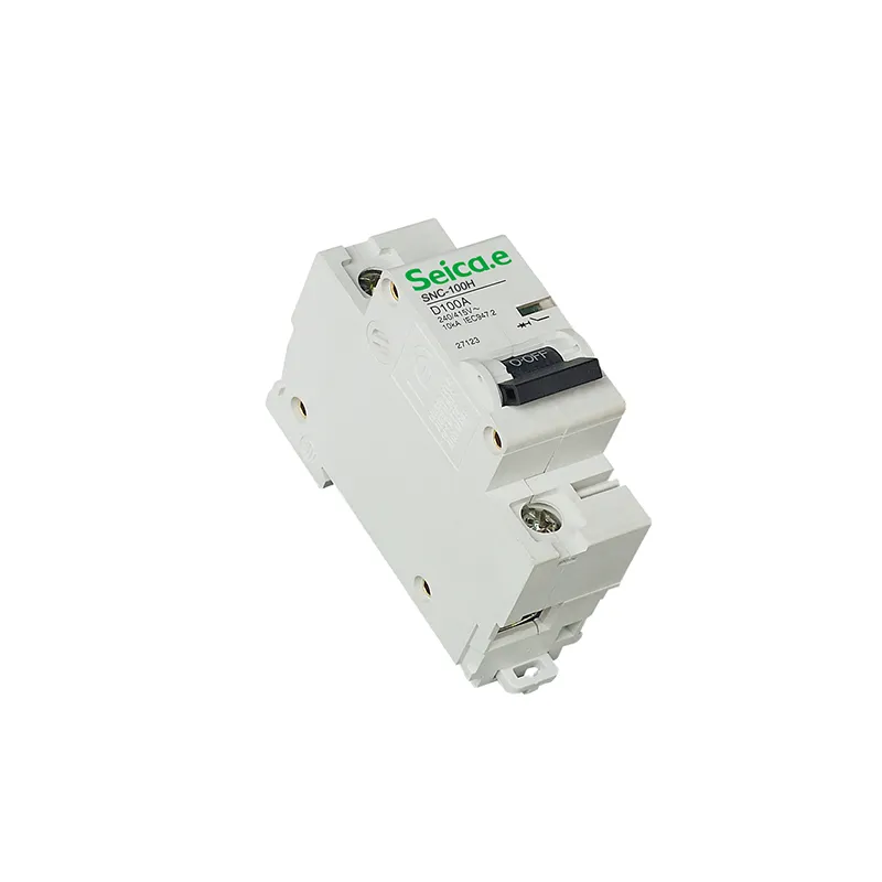
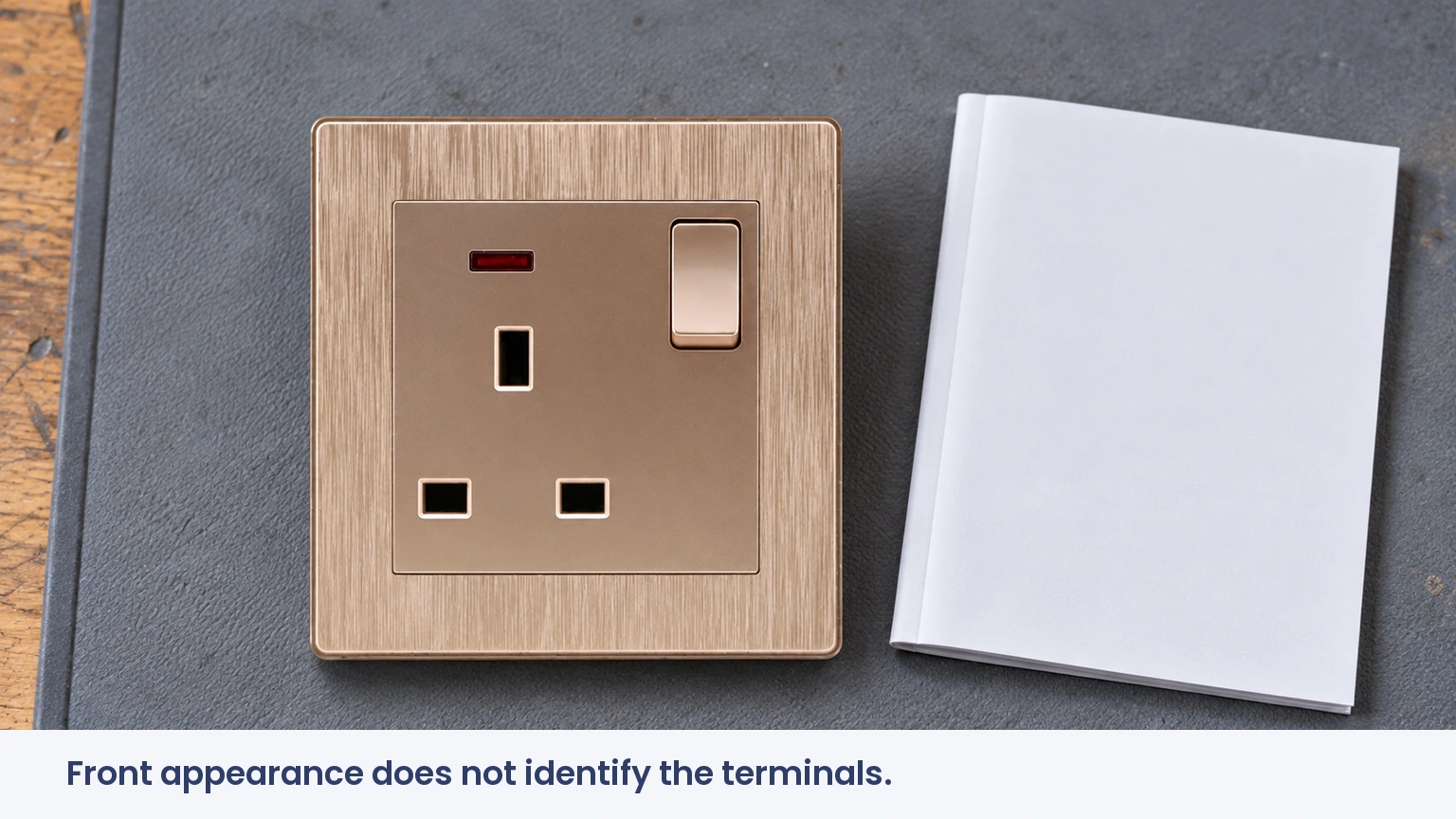
Other markets use different sockets, terminal markings and installation rules. A UK-style switched socket must not be wired from a US receptacle photograph. The illustrations here show accessory selection and inspection; the pictured decorative socket is not a NEMA wiring example.
Before removal, the electrician identifies every supply that can energize the box, isolates it, prevents accidental reconnection and proves dead with suitable equipment. HSE GS38 distinguishes proper voltage indication from tools that merely suggest a conductor may be live. A wall switch in the off position is not isolation, and a non-contact pen alone cannot prove the work area dead.
Which terminals carry hot, neutral and protective ground?
On many conventional US receptacles, brass identifies the hot terminal, silver identifies neutral, and green identifies equipment ground. These conventions help an electrician read the device; the exact manufacturer’s markings and wiring diagram remain decisive. Combination devices and protected receptacles can have additional terminals that cannot be interpreted from screw color alone.
For example, Leviton’s 5225 instructions distinguish hot, neutral, grounding and switch connections, with an intact or removed feed fin depending on the approved arrangement. That model uses 14–12 AWG conductors and specifies 14–18 in-lb terminal torque. Those numbers belong to that product, not to every receptacle or an unrelated supplier’s accessory.
Neutral and ground perform different jobs. Neutral carries normal return current; the equipment grounding conductor provides a protective fault path. Connecting them together at a downstream outlet can put normal current onto exposed bonded metal. A missing neutral or ground therefore needs a circuit-level solution under the applicable code, not a jumper added behind the faceplate.
How do terminal choice and mounting affect reliability?
The connection method must be approved for the conductor material, size and number of wires. A screw clamp, side screw and push-in terminal are not interchangeable instructions. Leviton’s published example includes a 5/8-inch stripping length, but another device may require a different length; exposed copper and trapped insulation are both reasons to correct a termination before energizing it.
- Confirm whether the terminal accepts copper, copper-clad or another specified conductor material.
- Use the stated stripping length and torque rather than judging tightness by feel.
- Keep cable retention, conductor space and protective bonding consistent with the enclosure and local code.
- Seat the device without pinching insulation, forcing conductors or using mounting screws to flatten a distorted box.
Mounting deserves its own check. A loose accessory moves whenever a plug is withdrawn, while an overfilled box can load the terminals mechanically. Replacing the front without addressing those conditions leaves the underlying maintenance problem in place.
What should be tested before the outlet returns to service?
A lamp turning on proves very little about the protective arrangements. Inspection and the appropriate dead tests come first; any necessary live testing then follows a controlled procedure. Under HSE GS38, live measurements need a reason and suitable equipment, not merely a convenient opportunity to check a repair.
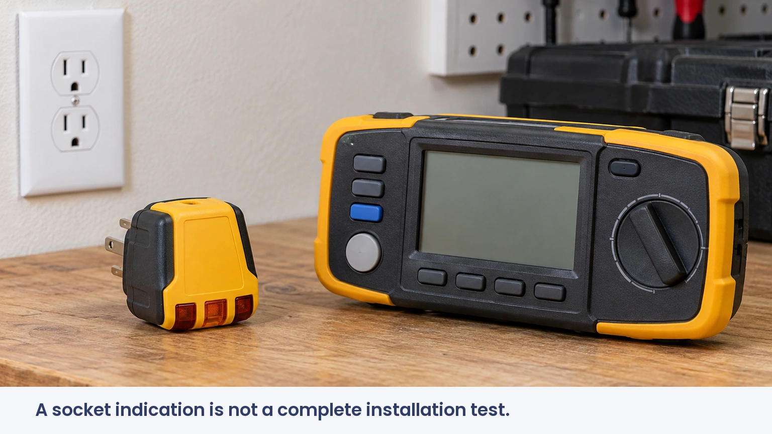
A simple plug-in outlet tester may indicate some wiring errors, but HSE warns that socket testers can miss faults and can falsely indicate safety. A satisfactory light pattern does not replace verification of protective-conductor continuity, the relevant fault-protection measures, insulation condition or RCD/GFCI operation where applicable.
What does each verification method actually establish?
| Method | Useful evidence | Important limitation |
|---|---|---|
| Visual inspection | Correct device, obvious damage, accessible markings | Cannot prove hidden conductor condition |
| Basic plug-in tester | Selected connection errors, depending on design | Does not certify the whole circuit |
| Voltage measurement | Potential difference at the test points | Normal voltage does not prove a reliable earth path |
| Installation verification | Recorded results against applicable requirements | Requires appropriate instruments and competent interpretation |
The financial difference is often a second visit. A cheap replacement followed by a call-back for a loose feed, unsuitable terminal or missing protective conductor may cost more than inspection and a properly scoped repair at the first visit.
When does a replacement become a larger wiring job?
| Condition found | What changes | Procurement consequence |
|---|---|---|
| Sound like-for-like replacement | Accessory and connection verification | Match rating, mounting and terminal requirements |
| Heat damage or brittle insulation | Repair may extend beyond the device | Allow investigation before ordering quantities |
| Missing required conductor | Circuit arrangement needs review | A different faceplate cannot solve the omission |
| New outlet location | Load, routing, protection and testing expand | Use an installation scope, not a replacement price |
Which standards and documents belong in the job file?
US projects should follow the locally adopted electrical code and the device’s recognized listing and instructions; a NEMA configuration identifies the connection pattern, not the entire installation approval. UK work follows applicable BS 7671 requirements, with GS38 informing safe test-equipment use. These are different jurisdictions, not alternative labels for the same compliance route.
CE, RoHS and GCC-market documents must be checked for the exact product and destination. They do not substitute for US approval or prove that a particular outlet has been correctly installed. A buyer should retain the model reference, instructions, relevant conformity documents and installation test record together.
How should a buyer select a replacement accessory?
- Start with the country, circuit and plug system, then choose the finish.
- Obtain the exact terminal instructions before releasing an order.
- Check box fit and conductor space, especially when upgrading an older accessory.
- Include inspection and testing in the quotation rather than treating them as optional extras.
ABUK’s socket and switch range provides a starting point for accessory sourcing; suitability depends on the selected model and project requirements. Projects that add a point rather than replace one should also consider the wider scope of adding an electrical outlet.
Frequently asked questions
How do you connect an electrical outlet?
A competent electrician isolates and proves the circuit dead, identifies the conductors, follows the exact device instructions, secures the accessory and completes the required verification before use.
Which terminal does the hot wire connect to on an outlet?
On many standard US receptacles it connects to the brass-marked hot terminal. The specific device diagram takes priority, particularly with combination or protected devices.
Why must the neutral and ground remain separate?
Joining them at a downstream receptacle can divert normal return current onto protective conductors and bonded metal. Their required system bonding location is determined by the supply arrangement and code.
How do I test outlet polarity after connection?
An electrician checks it using suitable instruments and the applicable verification procedure. A basic tester can screen for some errors; a normal outlet voltage alone does not establish correct polarity or safety.
References
- HSE: Electrical safety frequently asked questions
- HSE: GS38 electrical test equipment guidance
- Leviton: 5225 model ratings and installation documents
A reliable connection is one that can be explained, inspected and tested—not merely one that makes an appliance run. For accessory procurement, contact ABUK with the destination market, device requirements and installation constraints.